Ultra wideband antenna having frequency selectivity
a wideband antenna and ultra wideband technology, applied in the direction of antenna details, electrically long antennas, antennas, etc., can solve the problems of inconvenient operation, high cost, and inability to meet the requirements of wideband frequency range, and achieve the effect of avoiding the possibility of narrowband interference sources co-existing in a given environment, and avoiding the possibility of interference interference in the wideband
- Summary
- Abstract
- Description
- Claims
- Application Information
AI Technical Summary
Problems solved by technology
Method used
Image

Examples
first embodiment
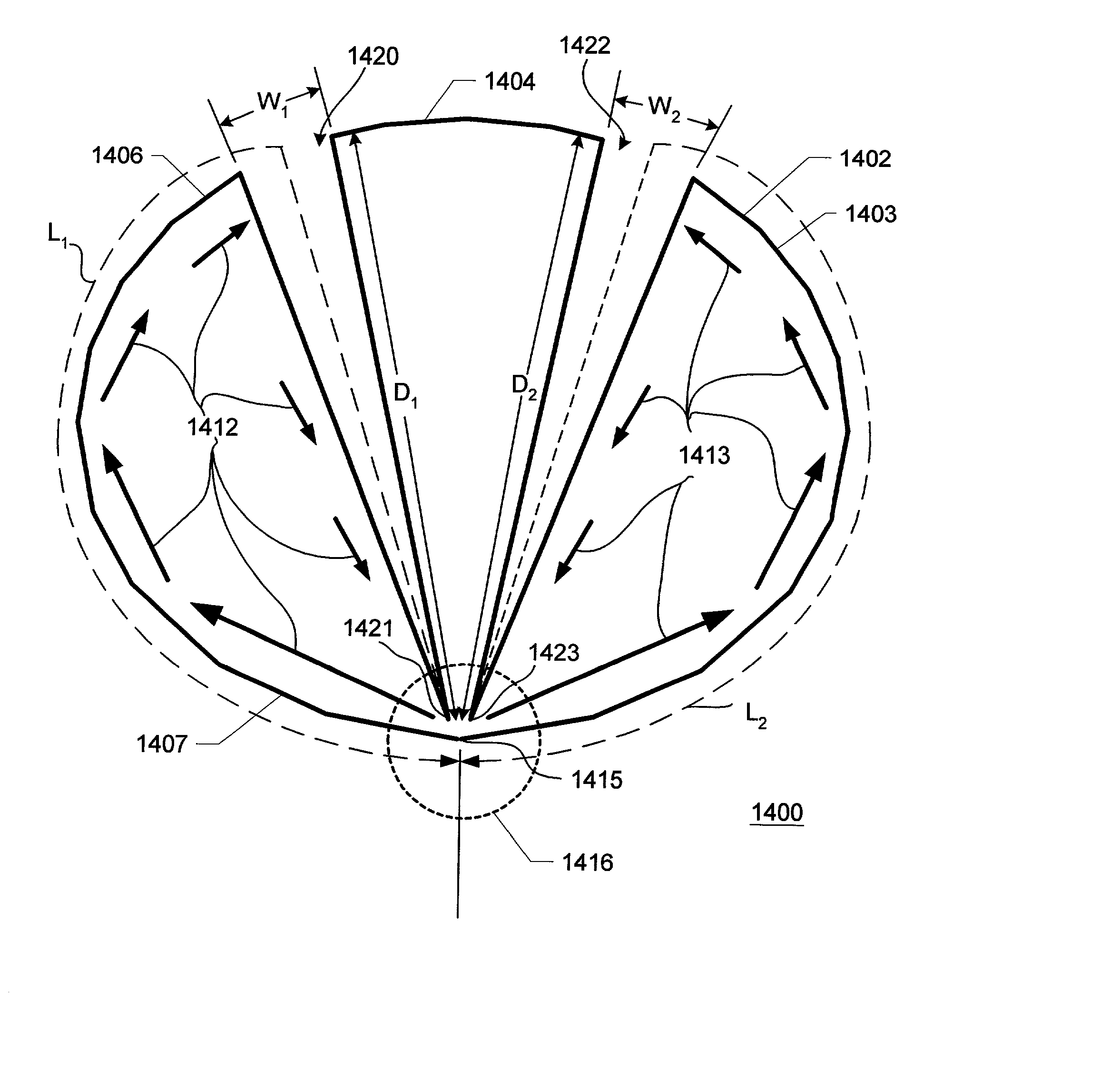
[0149] FIG. 14 illustrates the antenna apparatus of the present invention, including representative current flow within the apparatus. In FIG. 14, an antenna element 1400 is coupled for electromagnetic signal transfer (for reception or for transmission operation) substantially at a feed point 1415 in a feed region 1416 by a transmission line or similar radio frequency (RF) transmission structure (not shown in FIG. 14). Antenna element 1400 differs from prior art antenna element 1200 (FIG. 12) chiefly in the removal of notch areas 1420, 1422. Notch area 1420 is dimensioned with a width W.sub.1 and a depth D.sub.1 to an apex 1421. Notch area 1422 is dimensioned with a width W.sub.2 and a depth D.sub.2 to an apex 1423. Notch areas 1420, 1422 substantially divide antenna element 1400 into three antenna segments 1402, 1404, 1406. Antenna segments 1402, 1404, 1406 are commonly connected in the region of feed point 1415, but are increasingly widely separated as one departs from apexes 1421...
second embodiment
[0161] FIG. 16 illustrates the antenna apparatus of the present invention, including current flow within the apparatus. In FIG. 16, an antenna element 1600 is coupled for electromagnetic signal transfer (for reception or for transmission operation) substantially at a feed point 1615 in a feed region 1616 by a transmission line or similar radio frequency (RF) transmission structure (not shown in FIG. 16). Antenna element 1600 is configured with a notch area 1621. Antenna element 1600 includes a first antenna segment 1602 generally in the shape of a first ellipse having void area 1620 within its borders and skewed toward feed point 1615. Antenna element 1600 further includes a second antenna segment 1604 in the shape of a second ellipse smaller than the first ellipse (i.e., first antenna segment 1602). Antenna segment 1604 is situated within void area 1620 of first antenna segment 1602 and is generally tangentially arranged against an edge segment 1622 of edge 1603 of first antenna se...
third embodiment
[0171] FIG. 18 illustrates the antenna apparatus of the present invention embodied in a planar horn antenna structure. In FIG. 18, a horn antenna structure 1800 is carried on a substrate 1802. An antenna element 1803 integrally includes transceiving structures 1804, 1806. Transceiving structures 1804, 1806 establish a slotline structure 1810 between respective edges 1805, 1807. Antenna element 1803 is coupled for electromagnetic signal transfer (for reception or for transmission operation) substantially at a feed point 1815 in a feed region 1816 by a transmission line 1830 or similar radio frequency (RF) transmission structure.
[0172] Antenna element 1803 has a notch area 1820 extending from edge 1807 to an apex 1821. Notch area 1820 substantially divides transceiving structure 1806 to establish an antenna segment 1808. Antenna segment 1808 is commonly connected with transceiving structure 1806 in the region of feed point 1815; transceiving structure 1806 and antenna segment 1808 are...
PUM
 Abstract
Description
Claims
Application Information
 - R&D Engineer
- R&D Manager
- IP Professional
- Industry Leading Data Capabilities
- Powerful AI technology
- Patent DNA Extraction
Browse by: Latest US Patents, China's latest patents, Technical Efficacy Thesaurus, Application Domain, Technology Topic.
© 2024 PatSnap. All rights reserved.Legal|Privacy policy|Modern Slavery Act Transparency Statement|Sitemap