
Catheter positioning device

Inactive Publication Date: 2003-04-10
THERMOCORE MEDICAL SYST
View PDF19 Cites 53 Cited by
  • Summary
  • Abstract
  • Description
  • Claims
  • Application Information

AI Technical Summary

Problems solved by technology

The human vascular system may suffer from a number of problems.
Among the types of disease, atherosclerosis is a particular problem.
Additionally, the plaque may be inflamed and unstable, such plaque being subject to rupture, erosion or ulceration which can cause the patient to experience a myocardial infarction, thrombosis or other traumatic and unwanted effects.
Importantly, it has been reported that unstable and inflamed plaque can cause the temperature of the artery wall to elevate up to 2.5.degree. C. proximate the inflamed plaque.
Problems associated with systems incorporating a guide catheter include its relative positioning with respect to the catheter.
A problem may arise when the catheter is moved in the coronary arteries.
As the physician tries to maneuver the catheter in the cardiac tissue, this may cause the guide catheter to be pushed away from the entrance to the coronary artery, consequently causing the catheter to be dragged out of the coronary artery.
A problem associated with such a system is that the length of guide catheter remaining outside the patient is dependent on the size of the patient.
This poses a problem as, in use, the guide catheter and catheter must both be fixed to the positioning device in what is a fixed relative separation dictated by the physical dimensions of the positioning device and the lumen mounts.
Where positioning of the catheter, therefore translational movement within the vascular tissue (therefore also within the guide catheter and guide catheter extension) is required, the arrangement allows the junction between the guide catheter extension and guide catheter to be sealed by tightening the compression fitting, but does not allow the junction to impinge on the catheter within.
This will lead to loss of pressure, loss of blood, and unreliable pressure readings.

Method used


Image

  • Catheter positioning device
  • Catheter positioning device
  • Catheter positioning device

Examples


Embodiment Construction

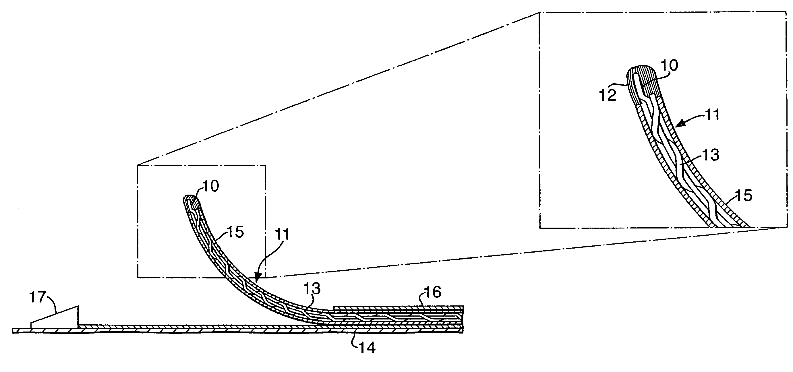
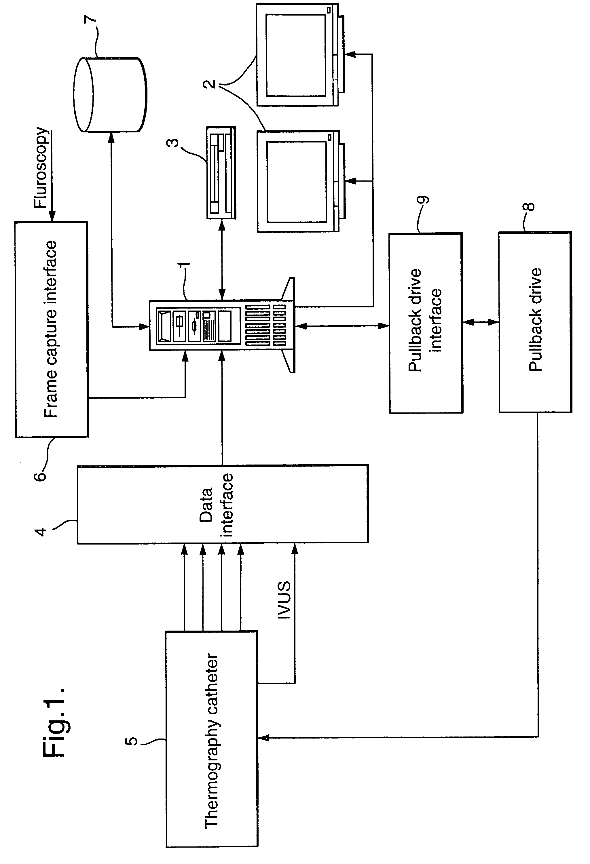
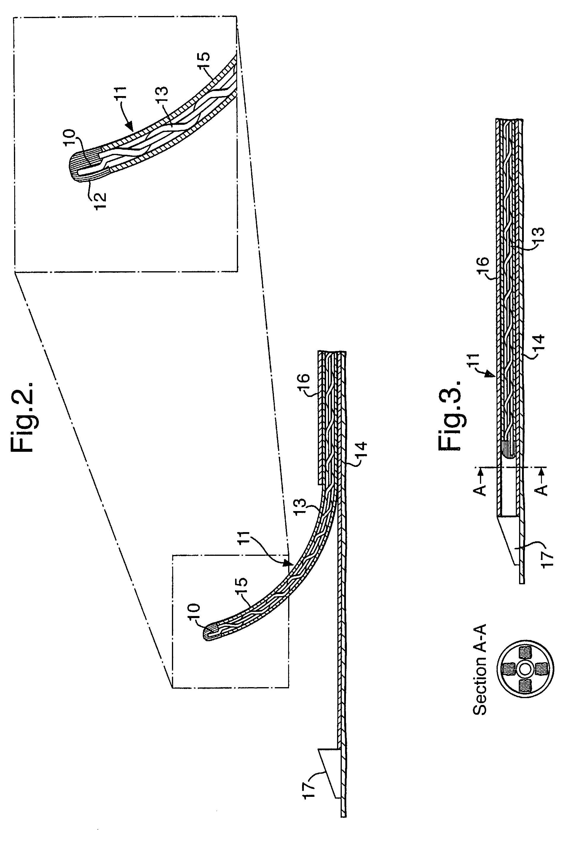
[0068] FIG. 1 is a schematic diagram of a system for conducting vascular catheterisation of a patient.

[0069] The system includes a personal computer (PC) 1 that presents a graphical user interface (GUI) via a number of monitors 2. The user interface system is based on a Microsoft Windows.TM. platform. Multiple windows may be used to acquire / project data from / to the user. Although not shown, the PC can accept user inputs via a keyboard and mouse, or other pointing device, in the usual manner. The PC includes a number of data stores 7, which may be external, and a CD ROM reader / writer device 3.

[0070] The PC is coupled via a data interface 4 to a thermography catheter 5, details of which will be described below. In this example, the thermography catheter 5 transmits four channels (one for each sensor) which are received by the data interface 4. An analogue temperature data signal on each channel is converted to a digital signal using an A / D converter within the data interface 4 at a us...


PUM


Abstract

A catheter positioning system comprises a guide catheter extension adapted to co-operate with a guide catheter, a catheter positioning device adapted to engage a catheter and guide the catheter within the guide catheter extension, wherein the guide catheter extension further comprises a plurality of engagement means for fixing the relative points of the guide catheter extension and the positioning device at any one of a number of positions over its length and a guide catheter extension capable of receiving a catheter, comprising a substantially rigid tubular section capable of sealing engagement within a compression fitting of the guide catheter.

Description

A CATHETER POSITIONING DEVICE[0001] This application claims priority from European Patent Application No. 01307682.3, filed Sep. 10, 2001, which is incorporated herein by reference. Also incorporated herein by reference are co-pending International Patent Application No. PCT / EP01 / 04401 and European Patent Application No. 01306599.0.[0002] 1. Technical Field[0003] The present invention relates to medical devices and methods for controlling the positioning of an intra vascular catheter device. In particular, the present invention is concerned with a positioning device for relative positioning of lumen in a multi-lumen intravascular catheter.[0004] 2. Background Art[0005] The human vascular system may suffer from a number of problems. These may broadly be characterised as cardiovascular and peripheral vascular disease. Among the types of disease, atherosclerosis is a particular problem. Atherosclerotic plaque can develop in a patient's cardiovascular system. The plaque can be quite ext...

Claims


Application Information

Patent Timeline
IPC IPC(8): A61B5/01A61M25/01A61M25/06
CPCA61M25/0662A61M25/0113
Inventor WILLIAMS, JOHN VAUGHANDIAMANTOPOULOS, LEONIDAS
Owner THERMOCORE MEDICAL SYST
Learn More