
Color filter substrate, manufacturing method thereof, liquid crystal device, and electronic apparatus

Inactive Publication Date: 2003-04-03
BOE TECH GRP CO LTD
View PDF0 Cites 35 Cited by
  • Summary
  • Abstract
  • Description
  • Claims
  • Application Information

AI Technical Summary

Benefits of technology

[0018] Accordingly, a color filter substrate for use in a transflective liquid crystal device can be provided which can improve the color purity of display in a transmission mode while the brightness and color purity of display in a reflection mode are not degraded.
[0047] Furthermore, when being provided with the liquid crystal device (transflective liquid crystal device) of the present invention described above, an electronic apparatus can be provided which can improve color purity of display in transmission mode while brightness and color purity of display in reflection mode are not degraded and which has superior image quality.

Problems solved by technology

The former liquid crystal device has an advantage in that display can be viewed in a dark place where outside light is not sufficient; however, since a backlight is always turned on, there has been a problem in that power consumption is increased.
In contrast, the latter liquid crystal device can save power since lighting means is not embedded therein; however, there has been a problem in that it is difficult to view displays in a dark place.
This results in lowering color purity.
As shown in FIGS. 20(a) and 20(b), in the conventional transflective liquid crystal device, the spectral characteristics of the color filter in a transmission mode and that of the color filter in a reflection mode are substantially different from each other, and compared to the case in which display is performed in a reflection mode, display performed in a transmission mode has a problem in that the color purity of display is low (range of color reproducibility is small).

Method used


Image

  • Color filter substrate, manufacturing method thereof, liquid crystal device, and electronic apparatus
  • Color filter substrate, manufacturing method thereof, liquid crystal device, and electronic apparatus
  • Color filter substrate, manufacturing method thereof, liquid crystal device, and electronic apparatus

Examples


first embodiment

[0069] First Embodiment

[0070] Structure of Transflective Liquid Crystal Device

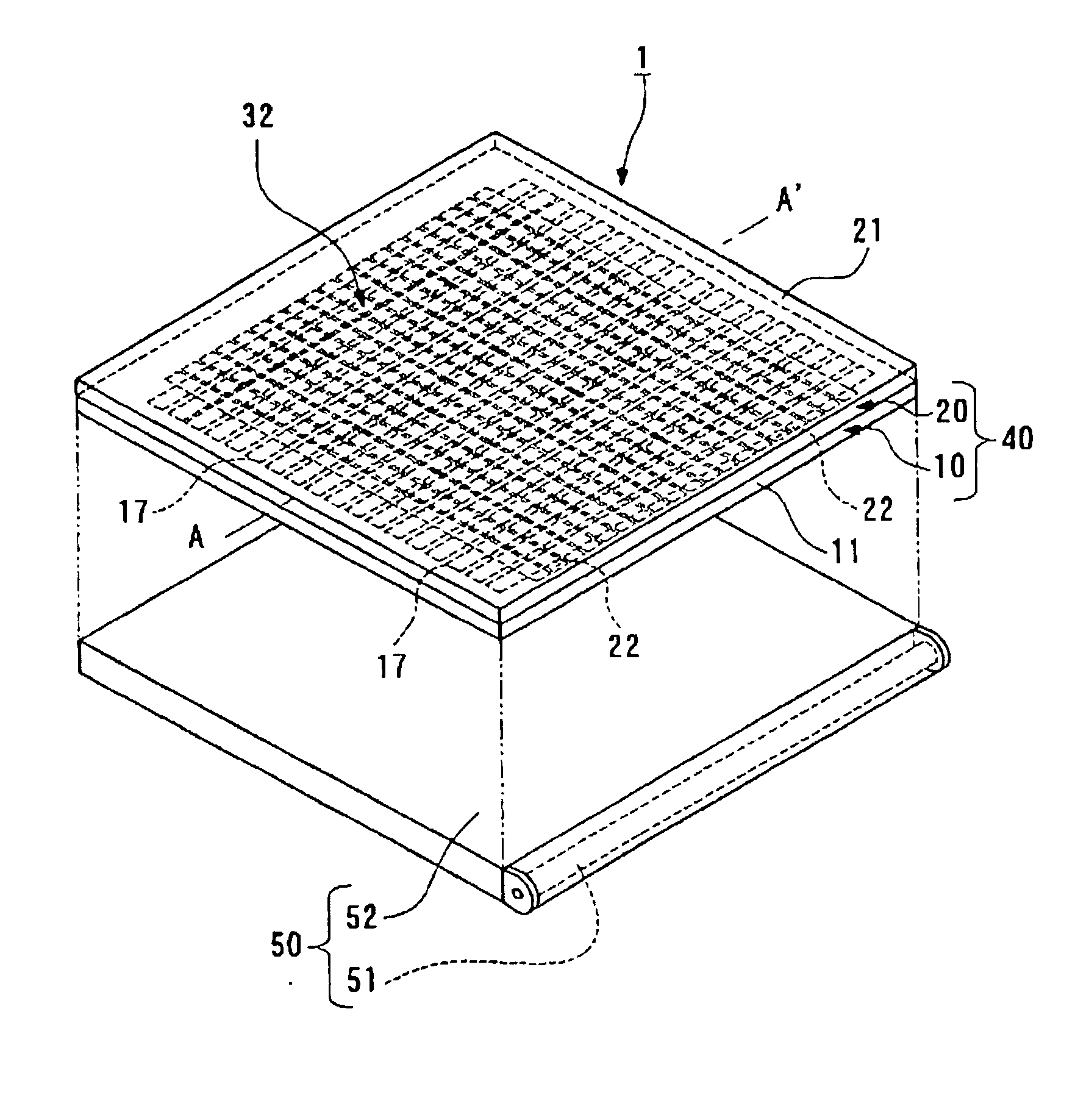
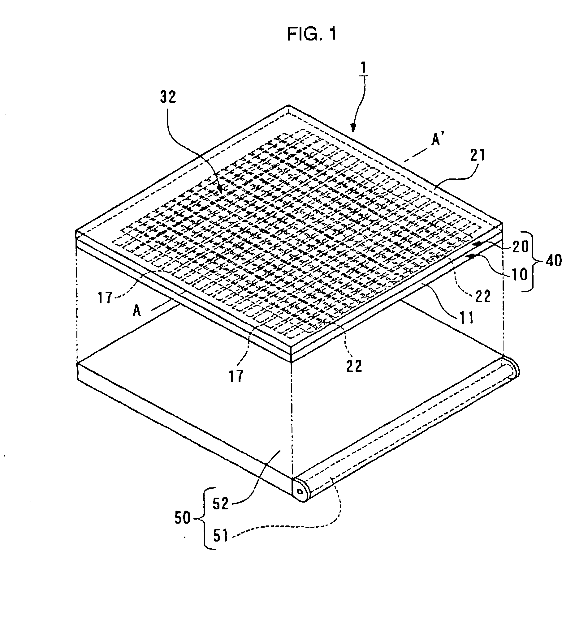
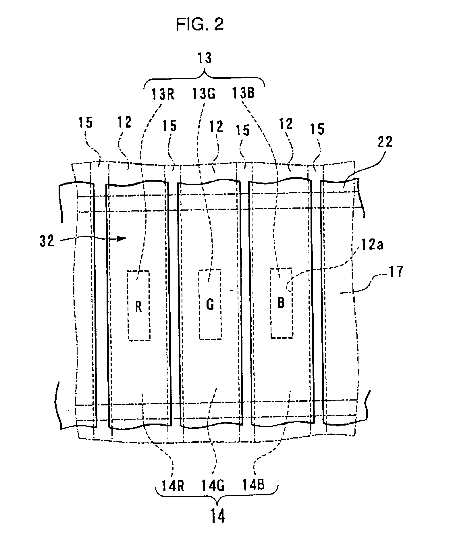
[0071] Referring to FIGS. 1 to 3, the structure of a transflective liquid crystal device of a first embodiment of the present invention will be described. In this embodiment, an example in which the present invention is applied to a passive matrix liquid crystal device will be described. In addition, the transflective liquid crystal device of this embodiment is provided with a color filter substrate of the present invention, and in particular, the structure thereof is characteristic.

[0072] FIG. 1 is a schematic perspective view showing the entire structure of the transflective liquid crystal device of this embodiment. FIG. 2 is a schematic plan view showing color filters and shading layers provided for the transflective liquid crystal device of this embodiment when viewed from the liquid crystal layer side. FIG. 3 is a partial, schematic, cross-sectional view of the transflective liquid crystal device take...

second embodiment

[0141] Second Embodiment

[0142] Structure of Transflective Liquid Crystal Device

[0143] Next, the structure of a transflective liquid crystal device according to a second embodiment of the present invention will be described. In this embodiment, as in the first embodiment, an example in which the present invention is applied to a passive matrix liquid crystal device will be described.

[0144] Since the primary structure of the transflective liquid crystal device of this embodiment is equivalent to that of the first embodiment, the same reference numerals of the constituent elements in the first embodiment designate the same constituent elements in this embodiment, and descriptions thereof are omitted. In addition, this embodiment will be described with reference to FIGS. 8 and 9, which correspond to FIGS. 2 and 3 in the first embodiment. FIG. 8 is a schematic plan view of the color filters, the shading layers, and partitions described later provided for the transflective liquid crystal ...

third embodiment

[0168] Third Embodiment

[0169] Next, the structure of a transflective liquid crystal device according to a third embodiment of the present invention will be described with reference to FIG. 12. In the first and the second embodiments, the passive matrix transflective liquid crystal devices are described by way of example, and in this embodiment, an example in which the present invention is applied to an active matrix transflective liquid crystal device which uses TFT (Thin-Film Transistor) elements functioning as a switching element will be described. FIG. 12 is an exploded, schematic, perspective view showing the entire structure of the transflective liquid crystal device of this embodiment. FIG. 12 is a view corresponding to FIG. 1 in the first embodiment, and a liquid crystal panel provided in the transflective liquid crystal device of this embodiment is only shown in this figure. In addition, in this embodiment, the upper side in the figure shows the observer side (viewing side)....


PUM


Abstract

A transflective liquid crystal device 1 of the present invention is formed of a liquid crystal panel 40 composed of a color filter substrate 10, a counter substrate 20, and a liquid crystal layer 30 provided therebetween, and a backlight (lighting means) disposed at the side opposite to a viewing side of the liquid crystal panel. The color filter substrate 10 is formed of transflective layers 12 each having light transmission portions and light reflection portions; first color filters 13 formed so as to correspond to the light transmission portions of the transflective layers 12; and second color filters 14 having spectral characteristics different from those of the first color filters 13 and being formed so as to correspond to the light reflection portions of the transflective layers 12.

Description

BACKGROUND OF THE INVENTION[0001] 1. Technical Field of the Invention[0002] The present invention relates to color filter substrates, methods for manufacturing color filter substrates, liquid crystal devices, and electronic apparatuses, and more particularly, relates to a transflective liquid crystal device which can improve color purity of display in a transmission mode while brightness and color purity of display in a reflection mode are not degraded and which has superior image quality.[0003] 2. Description of the Related Art[0004] As liquid crystal devices, there have been known a transmission type liquid crystal device which performs display using light emitted from a backlight embedded therein and a reflection type liquid crystal device which performs display using outside light such as sunlight. The former liquid crystal device has an advantage in that display can be viewed in a dark place where outside light is not sufficient; however, since a backlight is always turned on, ...

Claims


Application Information

Patent Timeline
IPC IPC(8): G02B5/08G02B5/00G02B5/20G02F1/1335G02F1/1343
CPCG02F1/133555G02F1/133514G02F1/1335
Inventor SUZUKI, NOBUTAKA
Owner BOE TECH GRP CO LTD
Learn More