
Multiple function spray nozzle

a spray nozzle and multi-functional technology, applied in the field of spray nozzles, can solve the problems of inconvenient use, inconvenient use, and insufficient versatility of conventional spray nozzles

Inactive Publication Date: 2003-03-06
LU KUO CHOU
View PDF0 Cites 41 Cited by
  • Summary
  • Abstract
  • Description
  • Claims
  • Application Information

AI Technical Summary

Benefits of technology

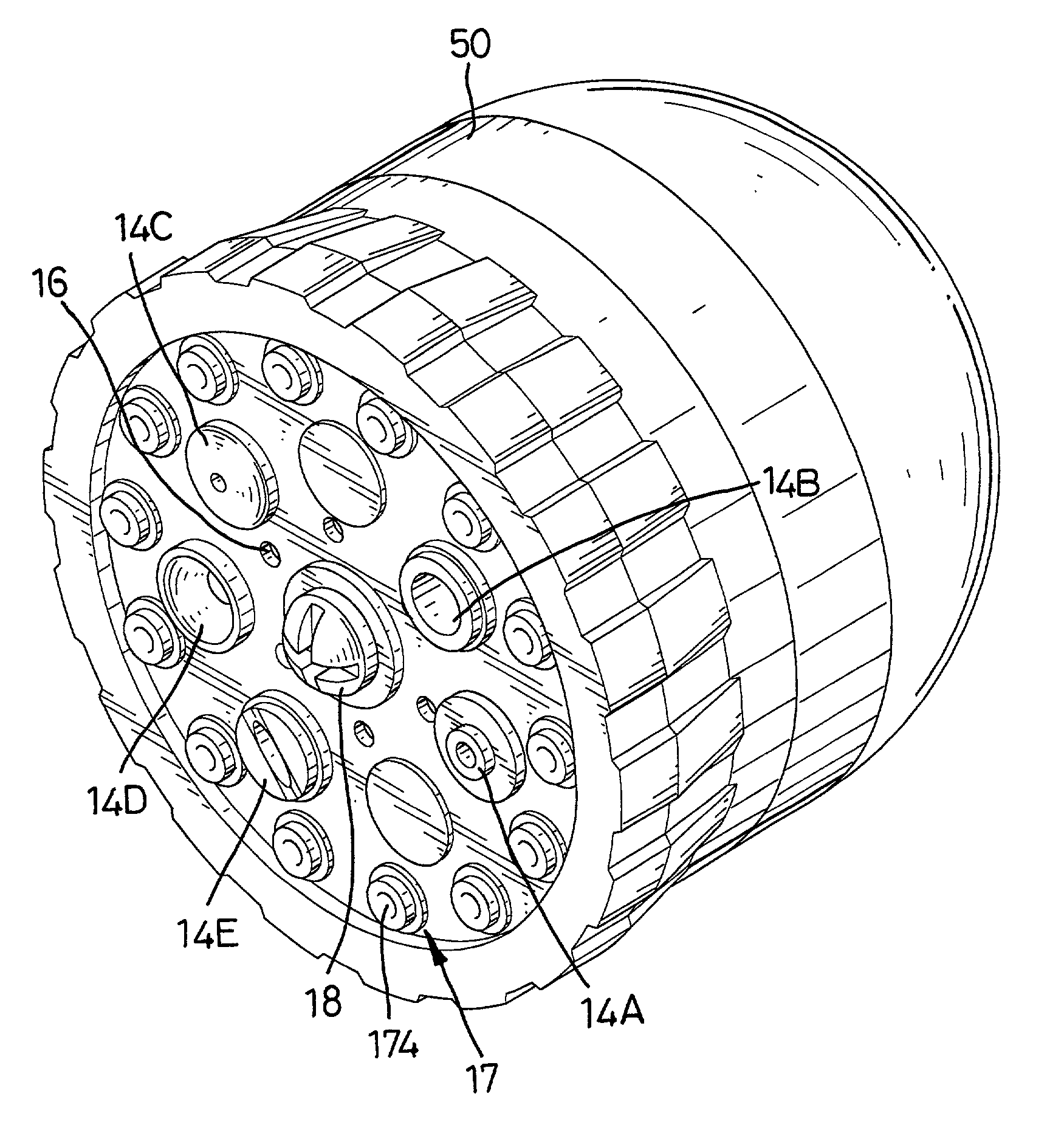
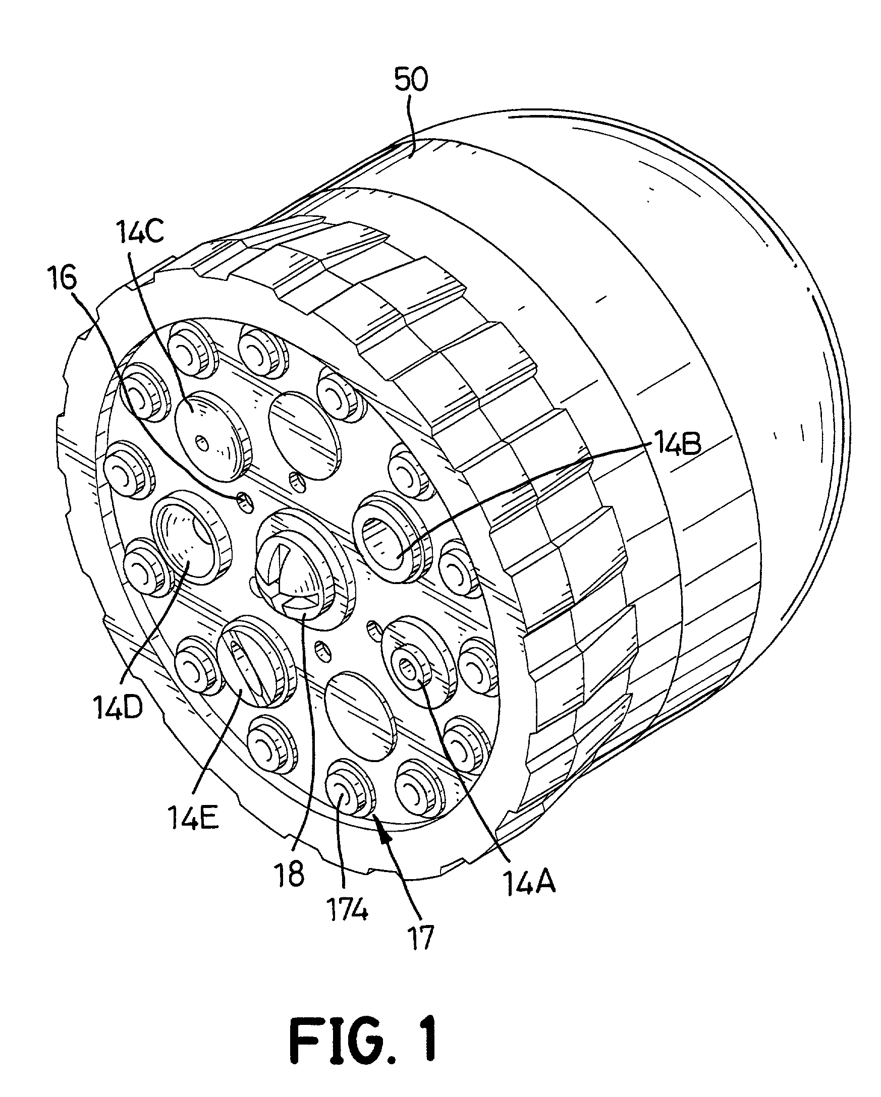
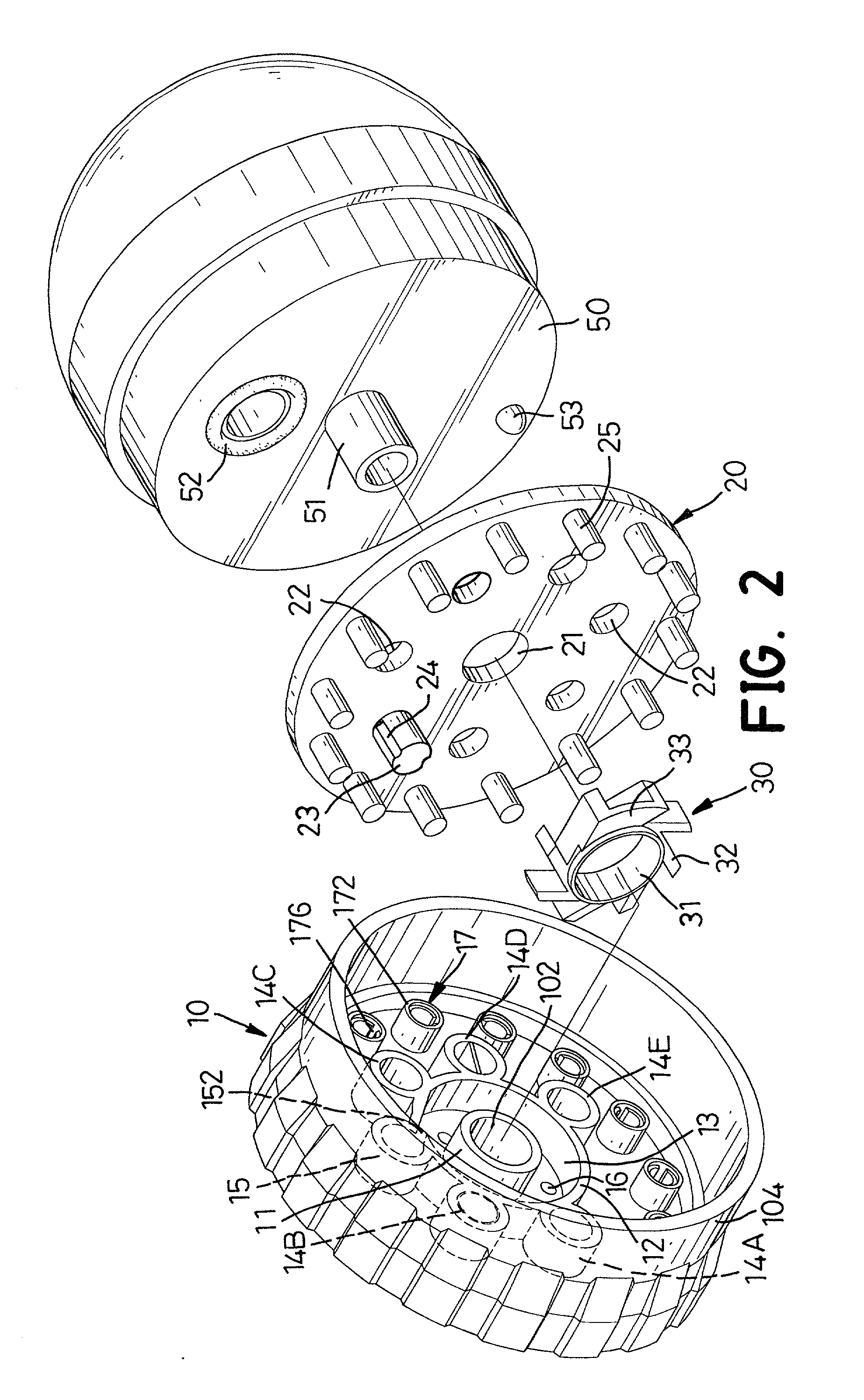
[0017] Multiple nozzle units (14A, 14B, 14C, 14D, 14E) are formed on an outer periphery of the baffle (12). One of the nozzle units (14A, 14B, 14C, 14D, 14E) can be a high pressure nozzle (14A), a soaker nozzle (14B), a misting nozzle (14C), a cone nozzle (14D) or a fan nozzle (14E). A closed tube (15) communicating with the inner space (13) in the baffle (12) is formed on the outer periphery of the baffle (12). A passage (152) is defined in the baffle (12) to allow the closed tube (15) to communicate with the inner space (13) inside the baffle (12). The passage (152) communicating between the inner space (13) and the close tube (15) is defined parallel to a tangent of the central ring (31) of the stream slicer (30). Accordingly, each blade (32) faces the passage (152), and the impacting area of each blade (32) is increased.

Problems solved by technology

However, the versatility of the conventional spray nozzle is not very good, and a spray nozzle with more capabilities is needed.

Method used


Image

  • Multiple function spray nozzle
  • Multiple function spray nozzle
  • Multiple function spray nozzle

Examples


Embodiment Construction

[0014] With reference to FIGS. 1 to 3, a spray nozzle in accordance with the present invention comprises a hollow head (50), a cap (10) and a middle plate (20). The head (50) is connected to a water source with a hose (not shown). A discharge channel (52) is defined in a first side of the head (50). A central tub (51) extends outward from the first side of the head (50).

[0015] The cap (10) is rotatably mounted on the central tube (51) on the head (50). A central tube (11) with a central passage (102) is formed on the cap (10) to mate with the central tube (51) on the head (50). A screw (18) extends into the central tubes (11,51) on the cap (10) and the head (50) to screw into an inner thread (not shown) defined in the head (50), such that the cap (10) is rotatably mounted on the head (50). A skirt (104) is formed around the edge of the cap (10) so that a space is defined inside the skirt (104). A circular baffle (12) is formed on the cap (10) around the central tube (11) on the side...


PUM


Abstract

A spray nozzle has a head, a cap and a middle plate. The head has a discharge channel. The cap is rotatably mounted on the head. A circular baffle is formed on the cap and has a space defined inside the baffle. Multiple nozzle units and a closed tube communicating with the space in the baffle are formed on the baffle. Multiple bores are defined in the cap and communicate with the space in the baffle. Multiple misting nozzles are mounted on the cap outside the baffle. The middle plate is secured in the cap. Multiple through holes are defined in the plate in a circle. Each nozzle unit on the baffle and the closed tube aligns with one of the through holes. Accordingly, the water can be sprayed from the spray nozzle in different forms. The using of the spray nozzle becomes more versatile.

Description

[0001] 1. Field of the Invention[0002] The present invention relates to a spray nozzle, and more particularly to a spray nozzle that can spray water in different forms.[0003] 2. Description of Related Art[0004] A spray nozzle connected to a water source through a hose is always used in the garden. The conventional spray nozzle in accordance with the prior art substantially comprises a head and a cap. The head is connected to the hose and has a discharge channel. The cap is rotatably mounted on the head. Multiple nozzle units like a high pressure nozzle, a soaker nozzle, a misting nozzle, a cone nozzle or a fan nozzle are mounted on the cap. When the cap is rotated and one of the nozzle units aligns with the discharge channel, water is sprayed from the aligned nozzle unit in a desired form. However, the versatility of the conventional spray nozzle is not very good, and a spray nozzle with more capabilities is needed.[0005] To overcome the shortcomings, the present invention tends to ...

Claims


Application Information

Patent Timeline
IPC IPC(8): B05B1/16B05B1/18B05B1/34B05B3/04
CPCB05B1/1654B05B1/18B05B1/3436B05B3/04
Inventor LU, KUO-CHOU
Owner LU KUO CHOU
Learn More