
Conveying apparatus

a technology of conveying apparatus and moving parts, which is applied in the direction of drying machines with progressive movements, charging, furniture, etc., can solve the problems of large increase in installation cost and enlargement of the apparatus

Inactive Publication Date: 2003-03-06
DAIFUKU CO LTD
View PDF0 Cites 25 Cited by
  • Summary
  • Abstract
  • Description
  • Claims
  • Application Information

AI Technical Summary

Benefits of technology

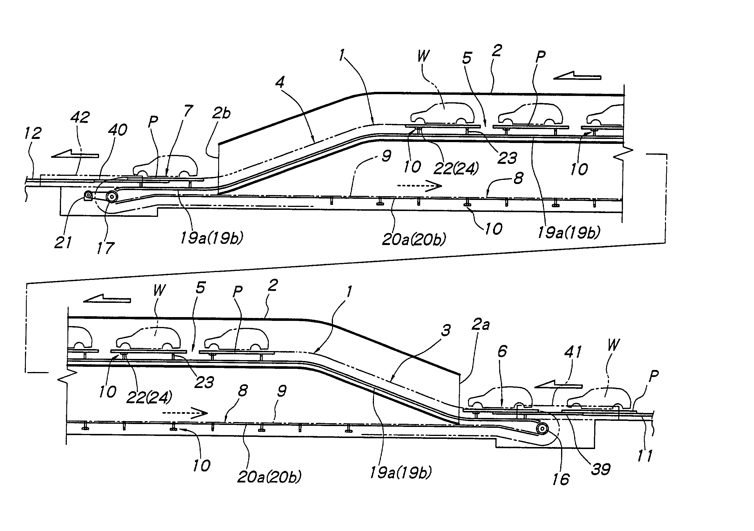
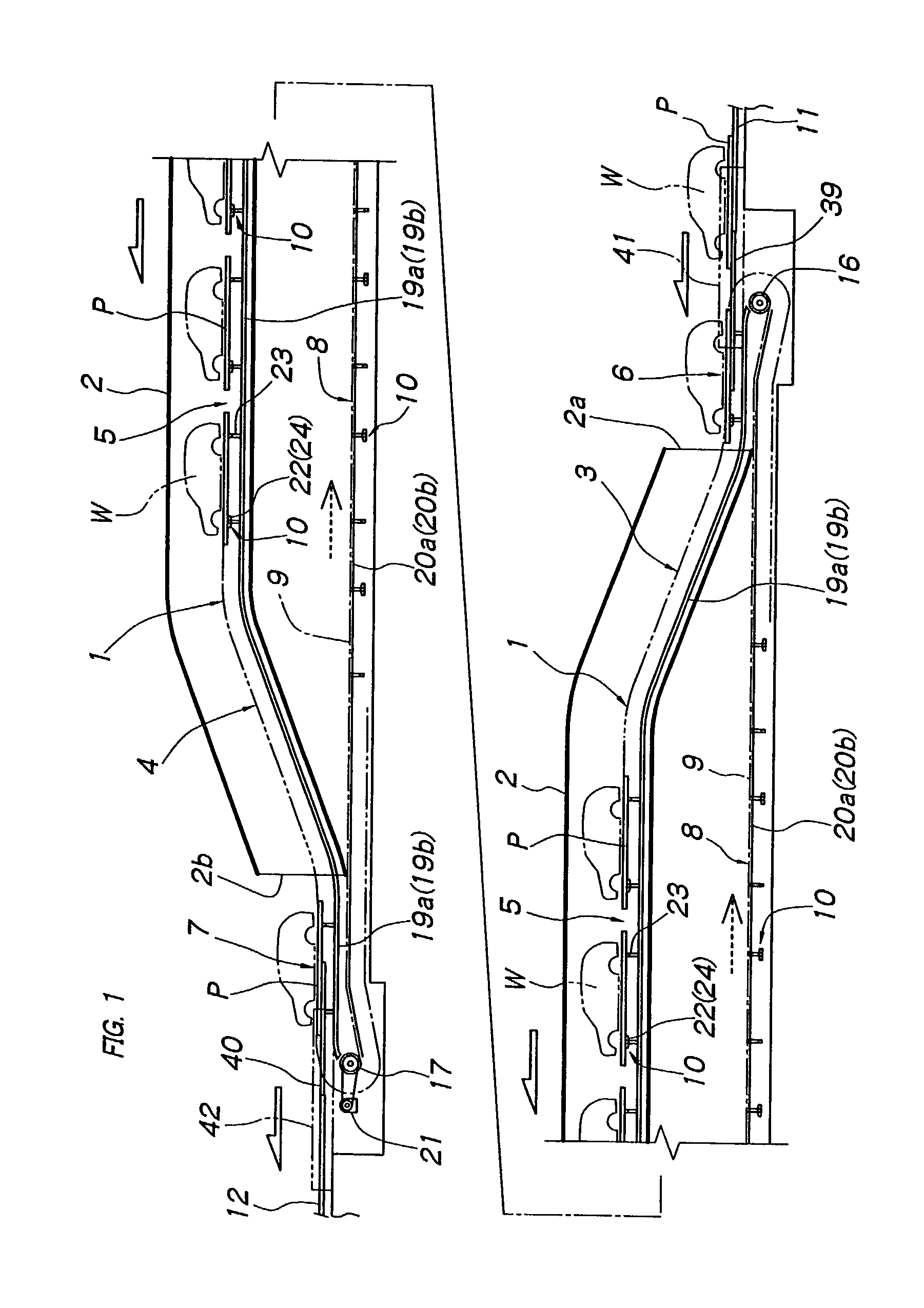
[0005] A load can be carried on the pallet, which may be supported and conveyed by a roller conveyor. By merely transferring the pallet to the horizontal inlet path section by a suitable means, it is possible to support the pallet on the pallet supporting and driving means, and convey the supported pallet along the inclined path section into a conveying path connected to the inclined path section and positioned at a different level. In other words, a common conveying means conveys the pallet along the inclined path section and the conveying path at the different level. This removes the need to provide an exclusive lifter or the like for lifting or lowering the pallet. Consequently, the cost for the installation may be greatly reduced. Additionally, the apparatus is easy to control. Pallets can be conveyed successively into the conveying path at the different level. As a result, the work cycle time can be greatly shortened.
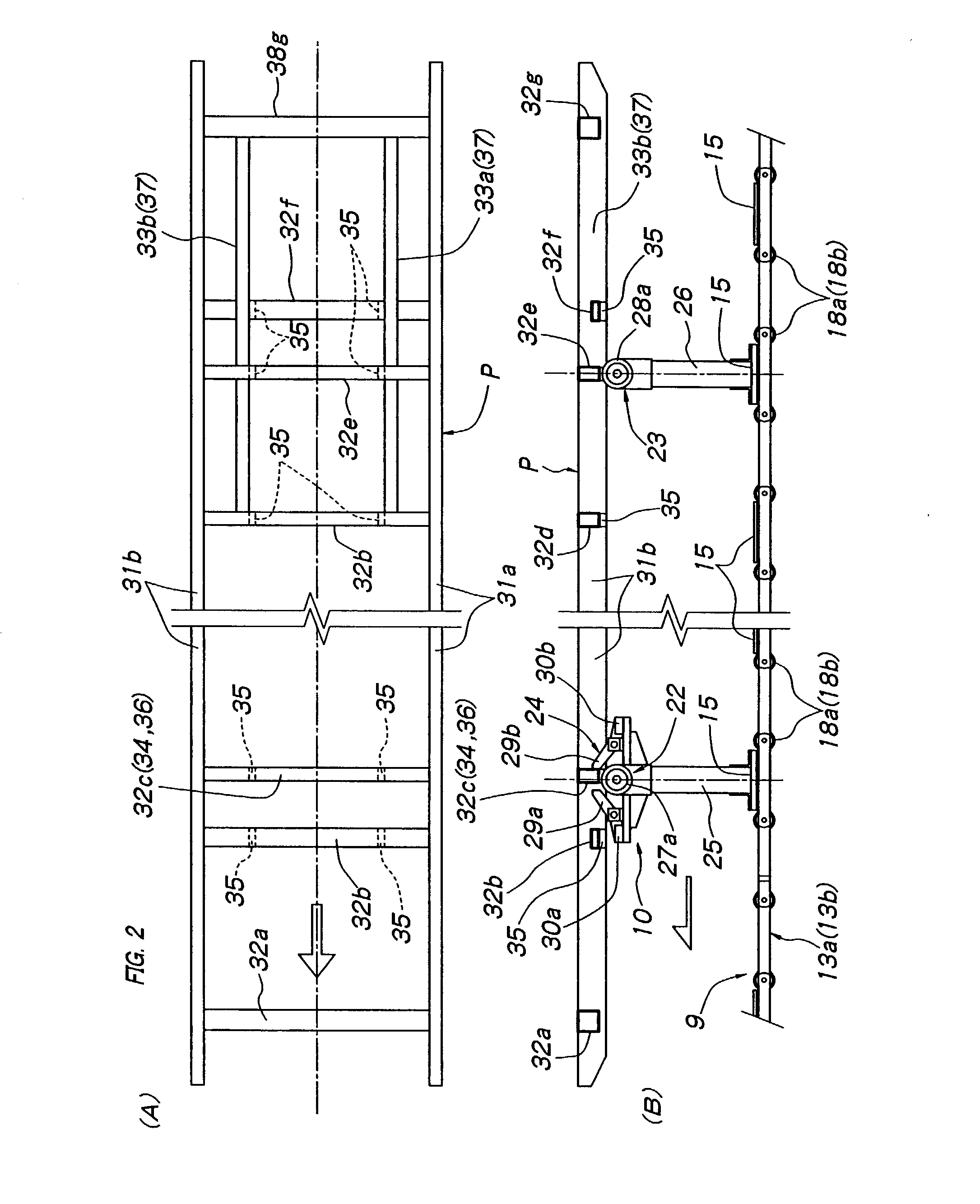
[0007] The roller rails can support the pallet in the horizontal inlet and outlet path sections. This makes it easy to transfer the pallet to the inlet path section and from the outlet path section. More specifically, the roller rails can support the side frames of the pallet. The cross frame, which connects the side frames, can function both as the front supported part that can be supported by the front pallet support, and as the engaged part that can engage with the driving engager. This enables the pallet to be simple in structure with only the longitudinal frames added as the rear supported part that can be supported by the rear pallet support.
[0009] The roller flanges can engage with the pallet grooves to laterally position the pallet supported and conveyed by the pallet supporting and driving means. Consequently, without a special positioner provided, the pallet can be conveyed safely without laterally deviating.
[0011] This structure makes it possible to convey the pallet reliably and safely at a predetermined speed in the predetermined direction, not only at the horizontal path sections, but also along the inclined path section, which may be either an up-grade path section or a down-grade path section.
[0013] This structure makes it possible to inexpensively produce a conveying apparatus that can be effectively used to convey large pallets.

Problems solved by technology

However, this results in enlargement of the apparatus and a great increase of the installation cost.

Method used


Image

  • Conveying apparatus
  • Conveying apparatus
  • Conveying apparatus

Examples


Embodiment Construction

[0020] The following sections describe exemplary embodiments of the present invention. It should be apparent to those skilled in the art that the described embodiments of the present invention provided herein are illustrative only and not limiting, having been presented by way of example only. All features disclosed in this description may be replaced by alternative features serving the same or similar purpose, unless expressly stated otherwise. Therefore, numerous other embodiments of the modifications thereof are contemplated as falling within the scope of the present invention as defined herein and equivalents thereto. Hence, use of absolute terms, such as, for example, "will," "will not," "shall," "shall not," "must," and "must not," are not meant to limit the scope of the present invention as the embodiments disclosed herein are merely exemplary.

[0021] A preferred embodiment of the present invention is described below with reference to the accompanying drawings. With reference ...


PUM


Abstract

The present invention provides a conveying apparatus for conveying in a predetermined direction loads supported on pallets in a drying furnace or the like. The conveying apparatus comprises a conveying path, a return path, an endless circulating driver and pallet supporting and driving means. The conveying path includes a horizontal inlet path, a horizontal outlet path, and an inclined path connected to at least one of the inner ends of the inlet and outlet path. The circulating driver circulates between the conveying path and return path. The supporting and driving means are mounted at intervals on the circulating driver. The pallet supporting and driving means include a front pallet support for supporting a front portion of the pallet, a rear pallet support for supporting a rear portion of the pallet, and a driving engager for automatically engaging with the pallet near the front pallet support. The pallet includes a front supported part that can be supported by the front pallet support, a rear supported part that can be supported by the rear pallet support movable relative to the pallet in the predetermined direction, and an engaged part for automatically engaging with the driving engager. The pallet conveyed to the inlet path section can be transferred onto one of the supporting and driving means, which conveys the pallet on it along the conveying path to the outlet path section.

Description

[0001] The present invention relates to a conveying apparatus suitable for conveying a number of coated car bodies or other loads supported on pallets in a drying furnace or the like.PRIOR ART[0002] Known conveying apparatus include a drying furnace through which loads successively pass and is installed between two conveying paths and positioned at a level higher than the paths. The inlet and outlet of the drying furnace are each provided with a lifting section for lifting and lowering the loads. This makes it possible to position the furnace inlet and outlet at a lower level in order to prevent heat from escaping out of the furnace through the inlet or outlet. Consequently, the thermal efficiency of the furnace can be higher. Such a drying furnace may be incorporated in a conveying line for conveying a number of loads on pallets supported and conveyed by a roller conveyor or the like. In this case, the inlet and outlet of the drying furnace need to be provided with large lifters fo...

Claims


Application Information

Patent Timeline
IPC IPC(8): B65G17/48B62D65/18B65G17/32B65G17/46B65G19/02B65G47/52F26B15/14F26B15/18
CPCB62D65/18B65G19/02F26B15/14F26B2210/12B65G17/48
Inventor KASAGI, MASAO
Owner DAIFUKU CO LTD
Learn More