
Concrete grindings reclamation system

a reclamation system and concrete technology, applied in the direction of filtering element filters, separation processes, filtration separation, etc., can solve the problems of inability to achieve the effect of reducing the number of contaminated materials, deteriorating and degrading roads, and affecting the quality of concrete grinding,

Inactive Publication Date: 2003-01-09
VARCO I P INC
View PDF0 Cites 18 Cited by
  • Summary
  • Abstract
  • Description
  • Claims
  • Application Information

AI Technical Summary

Benefits of technology

0022] New, useful, unique, efficient, nonobvious systems and methods for handling and treating a slurry with water and concrete grindings to reclaim constituents thereof for re-use and / or safe disposal;
0023] Such systems that use one or more vibratory separators and / or one or more decanting centrifuges; and

Problems solved by technology

The surface of concrete roadways often deteriorates and degrades so that the surface, which was relatively smooth when the roadway was made, becomes uneven and rough.
Today this is not feasible due to, among other things, the high pH of the material which renders it hazardous.

Method used


Image

  • Concrete grindings reclamation system
  • Concrete grindings reclamation system
  • Concrete grindings reclamation system

Examples


Embodiment Construction

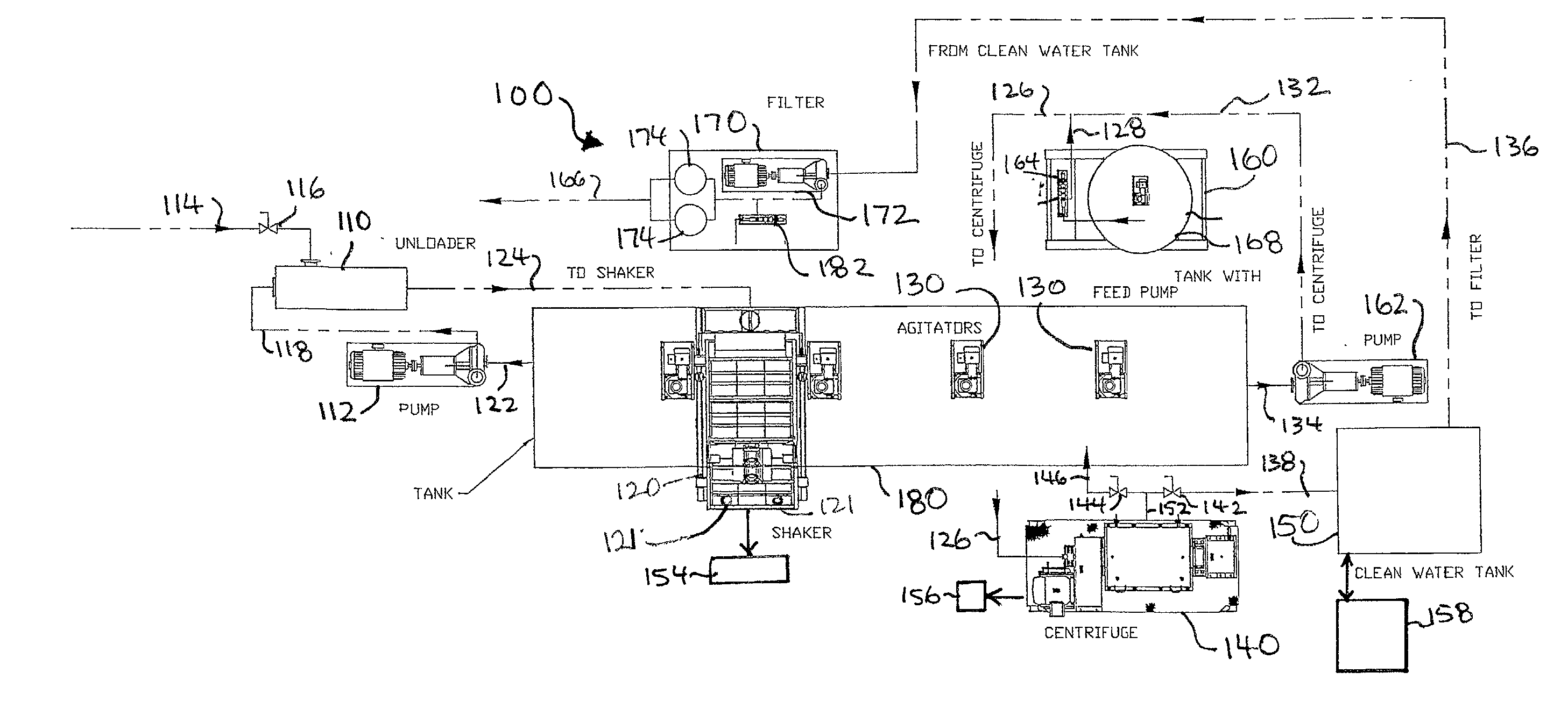
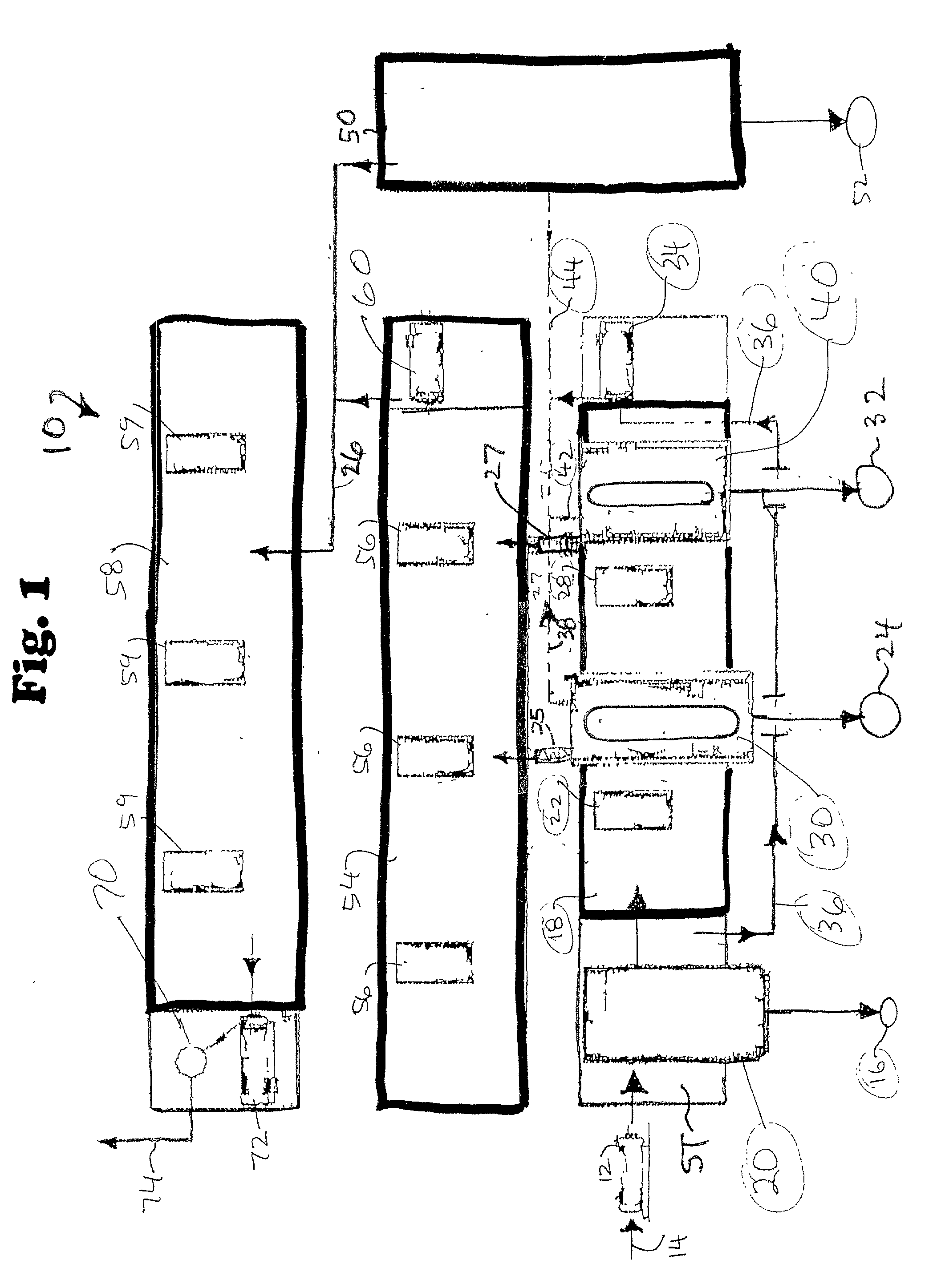
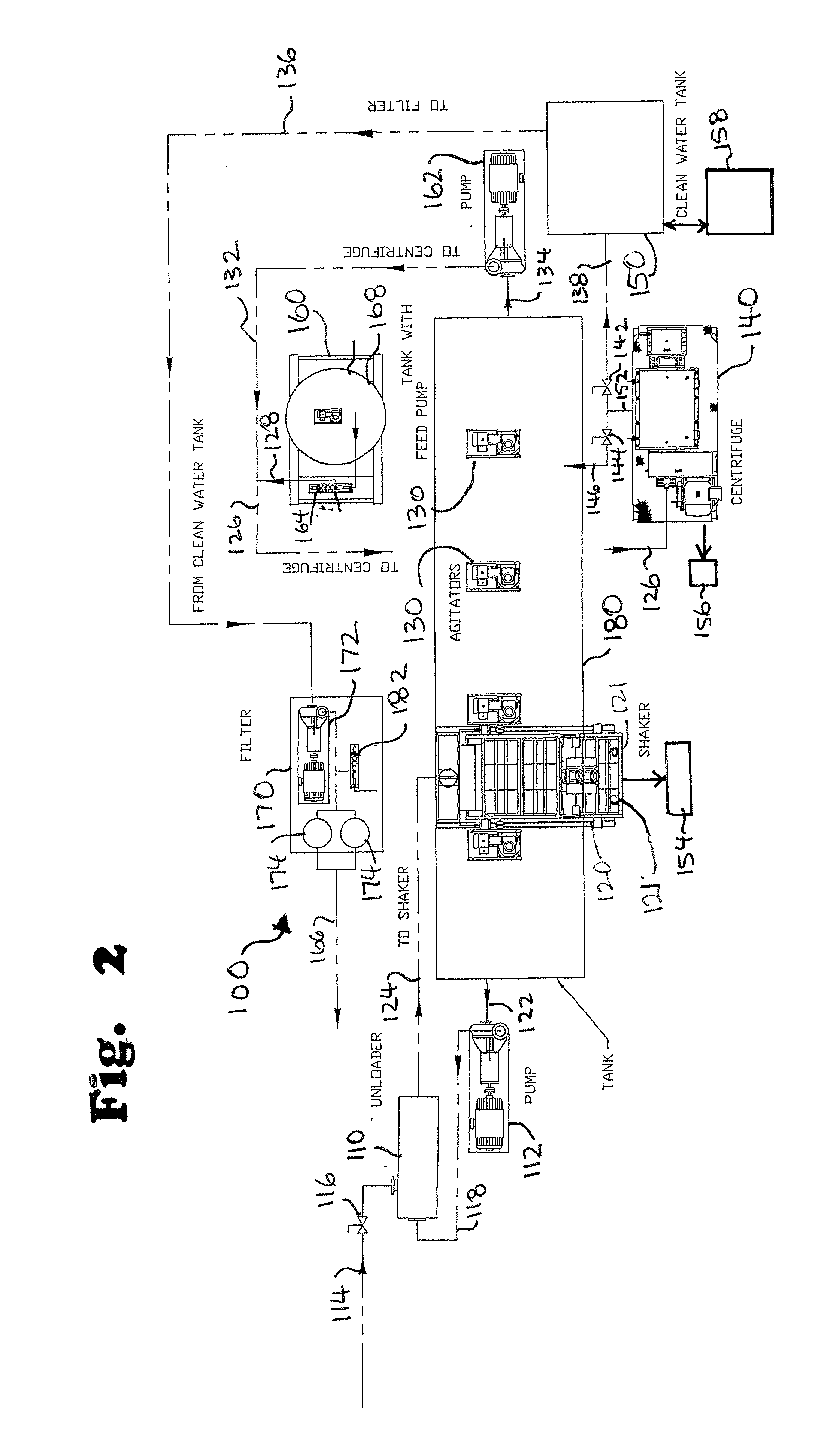
[0030] Referring now to FIG. 1, a system 10 according to the present invention has a pump 12 that pumps a concrete grindings slurry in a line 14 to a vibratory separator 20, e.g. but not limited to a commercially available Brandt King Cobra shale shaker with, e.g. 200 mesh screens or a Brandt Viper Shale Shaker. Alternatively, the concrete grindings or a slurry with them is gravity fed, e.g. but not limited to, from a truck to the shaker's feed hopper. Sand, cement particles, solids in the slurry, and concrete fragments screened out of the slurry by the vibratory separator 20 are collected in a bin 16. Fluid from the slurry that flows through the screen(s) of the vibratory separator flows through the shaker's screens into a tank 18 in which it is agitated by agitator apparatuses 22, 28 to maintain cement solids in suspension. The thus-agitated material is then fed to a centrifuge 30 and to a centrifuge 40. The centrifuges 30 and 40 operate in parallel to produce clear water effluent...


PUM

PropertyMeasurementUnit
sizeaaaaaaaaaa
sieve sizeaaaaaaaaaa

Abstract

A method for treating a fluid slurry with concrete grindings to separate constituents thereof, the constituents including water, sand and cement particles, the method including removing solids (e.g. large concrete fragments, rock, etc.) from fluid slurry with vibratory separation apparatus, the vibratory separation apparatus having screen apparatus for separating materials, the vibratory separation apparatus producing wet solids flowing off the top of the screen apparatus and a fluid stream containing water and cement particles, the fluid stream discharged beneath the screen apparatus, feeding at least a portion of the fluid stream to centrifuge apparatus, and separating cement particles from the fluid stream with the centrifuge apparatus and producing a stream of water with the centrifuge apparatus; and re-usable cement particles recovered using such a method.

Description

[0001] 1. Field of the Invention[0002] This invention is directed to: systems and methods for dewatering materials; to concrete treatment and reclamation; reclamation of components of solidified concrete and of slurries thereof; treatment of components of such mixtures; and disposal thereof.[0003] 2. Description of Related Art[0004] The surface of concrete roadways often deteriorates and degrades so that the surface, which was relatively smooth when the roadway was made, becomes uneven and rough. Such uneven rough surfaces can be smoothed out by removing a top portion of the roadway. In certain prior art systems grinding apparatus grinds away a top portion of such a concrete roadway. Ground off concrete is removed in a fluid slurry as the grinding operation proceeds.[0005] In the past, the fluid slurry has been dumped on the side of a roadway or transported from the site of the roadway to an earthen pit or landfill. Today this is not feasible due to, among other things, the high pH ...

Claims


Application Information

Patent Timeline
Patent Type & Authority Applications(United States)
IPC IPC(8): C02F1/38C02F1/52C02F1/66C02F11/121C02F11/147
CPCC02F1/385C02F1/5236C02F1/5254C02F1/66C02F11/121C02F11/14Y10S241/38C02F11/147
Inventor WILLIAMS, CLIFTON T.SORTEBERG, BARRY LYNN
Owner VARCO I P INC
Learn More