
Optical subassembly for optical communications

a technology of optical communication and sub-assembly, applied in the direction of optical elements, electromagnetic transceivers, instruments, etc., can solve the problems of affecting the assembly of transceivers and fiber communication connectors, and affecting the reliability of fiber optic cable connectors. , to achieve the effect of reducing back reflection

Inactive Publication Date: 2002-12-26
LUMENTUM OPERATIONS LLC
View PDF4 Cites 22 Cited by
  • Summary
  • Abstract
  • Description
  • Claims
  • Application Information

AI Technical Summary

Benefits of technology

The patent describes a technology that improves the transmission of optical data signals over fiber optic networks. It involves the use of additional optical elements, such as a glass plate and lenses, to direct and focus the laser light onto the fiber optic conductor, and to reduce back reflection. These elements help to ensure the proper illumination intensity of the optical signals and improve the overall quality of the transmitted data.

Problems solved by technology

The technical problem of this patent text is not specified and requires further analysis and interpretation.

Method used


Image

  • Optical subassembly for optical communications
  • Optical subassembly for optical communications
  • Optical subassembly for optical communications

Examples


Embodiment Construction

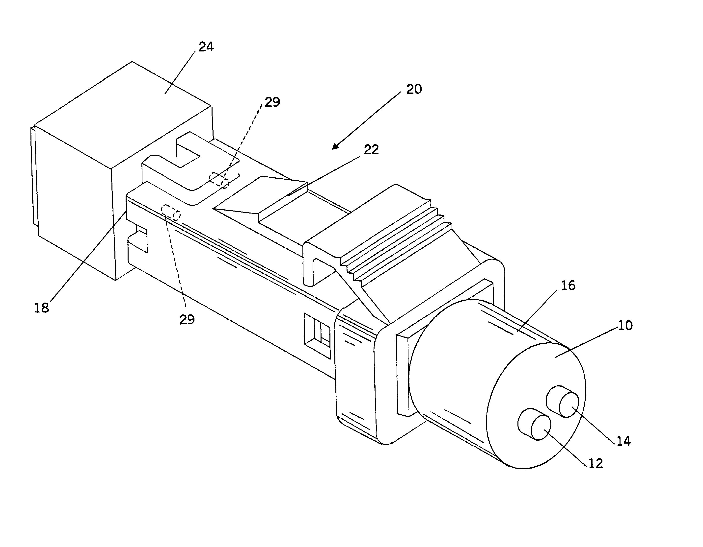
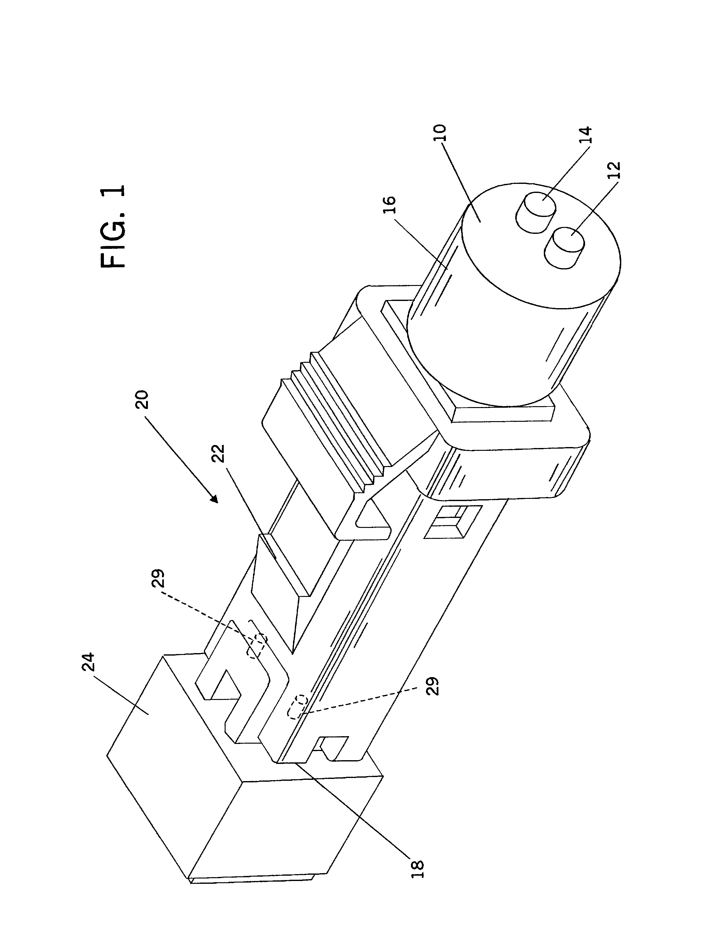
[0031] Referring initially to FIG. 1, a fiber optic cable 10, with two optical fibers 12, 14 contained within an external sheath 16, is provided to convey digital optical signals to and from an electronic device, such as a computer or network server (not shown). Optical fibers 12, 14 are terminated at the end 18 of a communications fiber optic cable plug 20. For purposes of illustration and description of the preferred embodiment of the invention, this disclosure and the preferred embodiment incorporate a MTRJ fiber optic cable plug 20. Because the MTRJ plug is manufactured to an industry standard, these MTRJ plugs are interchangeable with other such like plugs without regard to the source or manufacturer. Nevertheless, it must be understood that any style or type fiber optic cable plug may be used in conjunction with the invention; but MTRJ plugs permit a more densely populated array of transceivers and cable connections.

[0032] The fiber optic cable connector plug 20 is provided wi...


PUM


Abstract

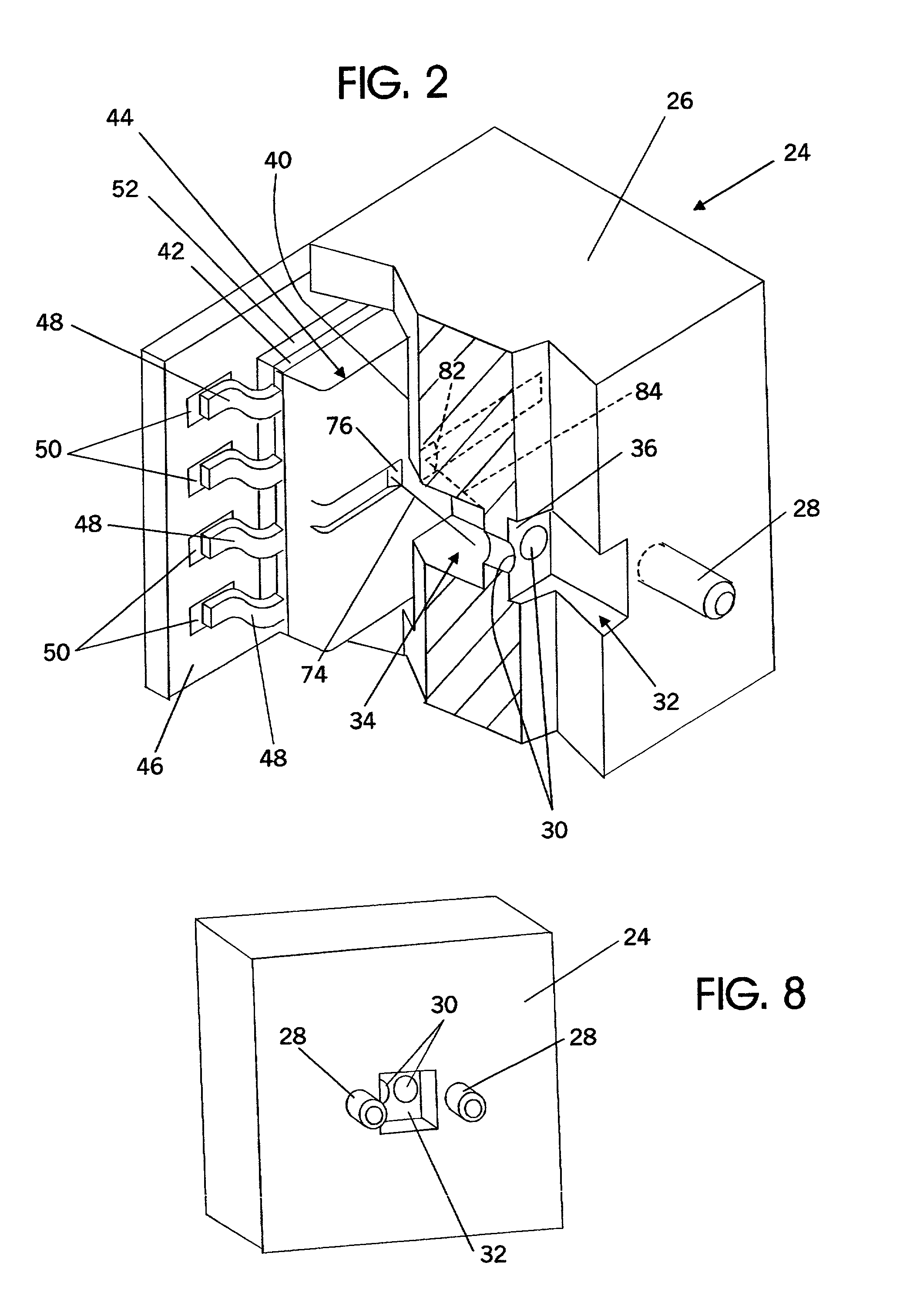
An optical signal transceiver subassembly is mounted on a lead frame for further attachment to an electronic printed circuit board. The optical subassembly is comprised of a solid-state laser, a pair of photo-detectors, an over-mold of transparent material having shapes forming the exposed surface thereof, the surface and a selective silvering of a portion thereof defining a beam-splitter mirror and an interior reflective focusing surface, preferably in the shape of a partial cylindrical surface. The beam-splitter mirror is lightly silvered and the cylindrical surface is silvered to enhance the reflection of the laser beam. The optical subassembly is further enclosed with a housing incorporating a pair of lenses and alignment pins. The lenses focus the data stream of optical light signals onto the end of the outgoing optical fiber and the data stream of optical light signals from the incoming optical fiber onto and through the beam-splitter and onto a first photo-detector. The beam-splitter and the partial cylindrical surface reflect the laser beam portion deflected from the primary laser beam path onto a second photo-detector to provide a data stream from which the operation of the laser may be monitored, thereby insuring the proper transmission of the data signals provided to the laser through the lead frame and its associated electronic connections.

Description


Claims


Application Information

Patent Timeline
Owner LUMENTUM OPERATIONS LLC
Learn More