Eureka AIR delivers breakthrough ideas for toughest innovation challenges, trusted by R&D personnel around the world.

Fluid cat cracking with high olefins production

a technology of flue cat and high olefins, which is applied in the direction of hydrocarbon oil cracking process, hydrocarbon oil treatment products, physical/chemical process catalysts, etc., can solve the problems of high cost of adding additional vessels to an existing fcc unit, limited olefin yield from the cracking reaction,

Inactive Publication Date: 2002-12-19
EXXON RES & ENG CO
View PDF8 Cites 54 Cited by
  • Summary
  • Abstract
  • Description
  • Claims
  • Application Information

AI Technical Summary

Benefits of technology

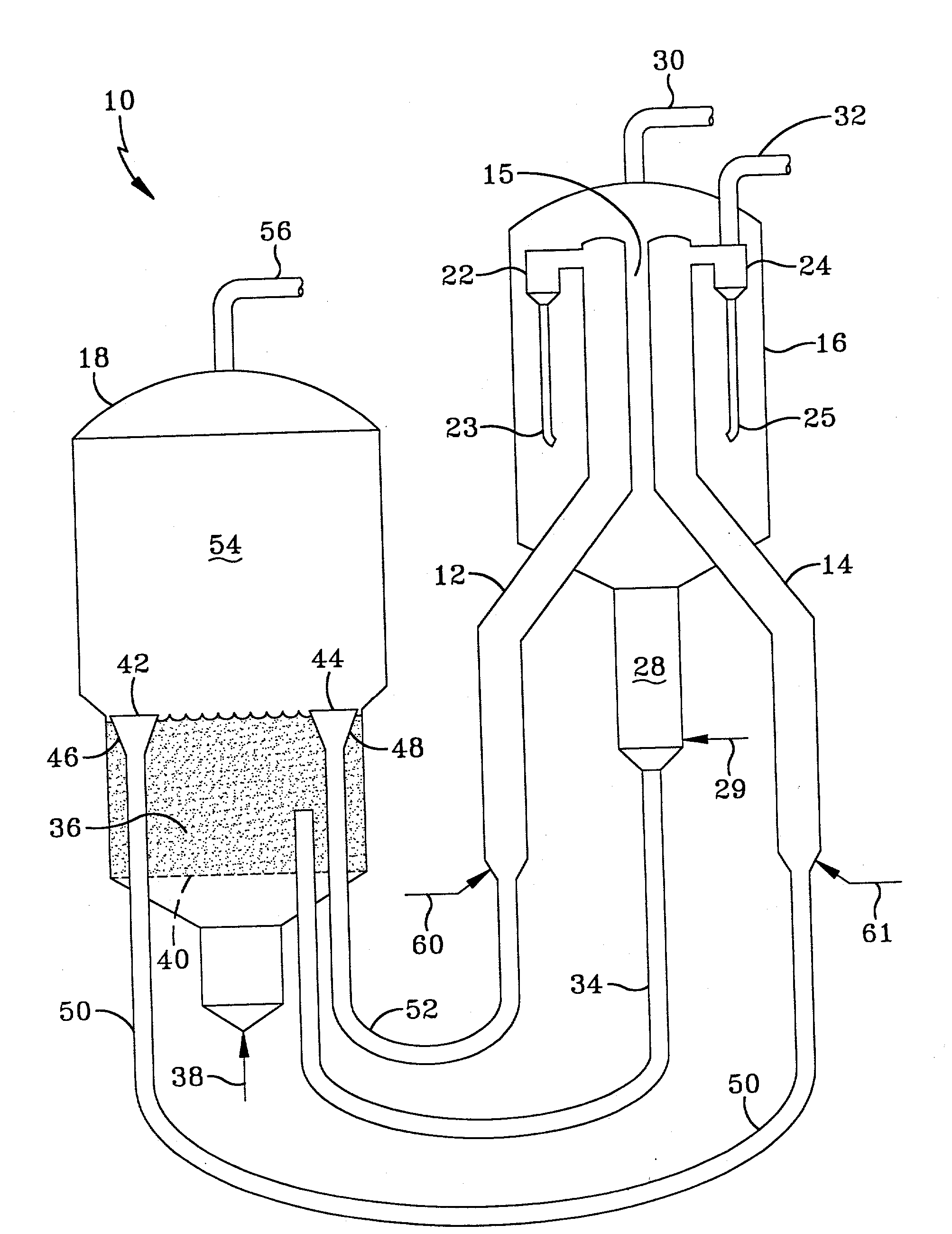
[0012] The separated, lower boiling hydrocarbons produced in each cracking zone are passed to product recovery operations, which typically include condensation and fractionation, to condense and separate the hydrocarbon products of the cracking reactions into the desired boiling range fractions, including naphtha and light olefins. By light olefins in the context of the invention, is meant comprising mostly C.sub.2, C.sub.3 and C.sub.4 olefins. In preferred embodiments, (i) the catalyst will comprise the preferred catalytic components referred to above, (ii) the naphtha feed to the second riser will boil within the range of from 60-300.degree. F. (15-149.degree. C.) for maximized light olefins production, and (iii) the reaction products of the cracking reactions in the second riser will not be mixed with the first riser reaction products, but will be passed to separate product recovery. The naphtha riser reaction products will be sent to the same separation vessel as the FCC feed riser reaction products, but will be passed into a different separation means within said vessel, from which the separated hydrocarbon vapors are removed. In a further embodiment, steam may also be injected into the naphtha riser cracking reaction zone, either admixed with the naphtha feed or separately injected. Propylene yield from the process of this invention may be up to three times that of a typical FCC process without the naphtha crackate riser reaction zone.

Problems solved by technology

Typical FCC cracking catalysts are based on zeolites, especially the large pore synthetic faujasites, such as zeolites X and Y. The olefins yield from the cracking reaction is limited by the process and cracking catalyst.
While it is possible to build a new FCC unit with additional risers and vessels for increased light olefins production, it is extremely costly to add additional vessels to an existing FCC unit.

Method used


Image

  • Fluid cat cracking with high olefins production

Examples


Embodiment Construction

[0022] A commercial FCC unit operating with only an FCC feed riser and a cracking catalyst which comprised a mixture of ZSM-5 and a USY zeolite-containing catalyst, was compared with the process of the invention (Base+), using data generated in pilot plants. The commercial unit was processing a vacuum gas oil feed (API=20.8), using a catalyst blend of a commercial USY-containing catalyst and a commercially available ZSM-5 catalyst. The blend contained about 34 wt. % of a USY zeolite and 0.2 wt. % ZSM-5. The MAT activity of this catalyst blend was 71. With a riser outlet temperature of 975.degree. F. (524.degree. C.) and a catalyst to oil weight ratio of 5, the yields obtained in the Table below, under BASE FCC, were achieved.

[0023] Two different pilot plants were used to demonstrate the improved FCC process of the invention. A circulating pilot plant was used to simulate the primary riser for cracking fresh feed and a bench scale unit was used to crack 60-430.degree. F. boiling rang...


PUM

PropertyMeasurementUnit
unit cell sizeaaaaaaaaaa
mole ratioaaaaaaaaaa

Abstract

The propylene production of a fluid catalytic cracking unit employing a large pore zeolite cracking catalyst, produces more propylene by adding a naphtha cracking riser and a medium pore zeolite catalytic component to the unit, and recycling at least a portion of the naphtha crackate to the naphtha riser. The large pore size zeolite preferably comprises a USY zeolite and the medium pore size is preferably ZSM-5. Propylene production per unit of naphtha feed to the naphtha riser is maximized, by using the 60-300° F. naphtha crackate as the feed.

Description

[0001] This application is a continuation-in-part of U.S. patent application Ser. No. 09 / 222,864 filed Dec. 30, 1998.[0002] The invention relates to a fluid cat cracking process for high olefins production, using a combination of dual risers and a cracking catalyst containing both large and medium pore zeolites. More particularly, the invention relates to a fluid cat cracking process using a cracking catalyst having faujasite and ZSM-5 components, to produce reaction products comprising light olefins and naphtha in a first riser. At least a portion of the naphtha is recovered and passed into a second riser, in which it is catalytically cracked to produce more light olefins.BACKGROUND OF THE DISCLOSURE[0003] The demand for light olefins, such as propylene and butylenes, and particularly propylene, is increasing faster than present plant capacity. A major source of propylene is from fluid cat cracking (FCC) processes. Fluid cat cracking is an established and widely used process in the...

Claims


Application Information

Patent Timeline
Patent Type & Authority Applications(United States)
IPC IPC(8): C10G11/05B01J29/40C10G11/18C10G51/02
CPCC10G2400/20C10G11/18
Inventor HENRY, B. ERIKWACHTER, WILLIAM A.SWAN, GEORGE A. III
Owner EXXON RES & ENG CO
Why Eureka
Eureka Blog
Learn More