Method for measuring flow rate of a continuous fluid flow

a continuous fluid flow and flow rate technology, applied in the direction of liquid/fluent solid measurement, instruments, machines/engines, etc., can solve the problems of occlusion of no prior art milk flow meters provide for reducing mastitis, etc., to improve the health of the animal or cow, prolong the use of the milk flow meter, and stable vacuum level

Inactive Publication Date: 2002-10-24
TECH HLDG +1
View PDF0 Cites 26 Cited by
  • Summary
  • Abstract
  • Description
  • Claims
  • Application Information

AI Technical Summary

Benefits of technology

0037] Another advantage of the present invention is that the milk flow meter may include a first detector for measuring the height of a selected section of a substantially continuous milk flow at a first predetermined location and a second detector determined that the selected section has traversed and the elapsed time therefor over a known distance between the first detector and second detector and a processing apparatus derives the cross-sectional area of the selected section and determined the milk flow rate from the derived cross-sections area and elapsed time.
0038] Another advantage of the present invention is that the milking flow meter can be located between a milk claw and pipeline in a milking system having a substantially stable vacuum level.
0039] Another advantage of the present invention is that the prolonged used of the milk flow meter of the preferred embodiment resulted in an improvement of the health of the animal or cow.
0040] Another advantage of the present invention is the use of a milk flow meter of the present invention helps to eliminate mastitis and leads to grea

Problems solved by technology

Further, none of the know prior art milk flow meters prevent occluding of the conduit within the meter to prevent flooding and collapsing of vacuum in a vacuum regulated milking system.
Fur

Method used


Image

  • Method for measuring flow rate of a continuous fluid flow
  • Method for measuring flow rate of a continuous fluid flow
  • Method for measuring flow rate of a continuous fluid flow

Examples


Embodiment Construction

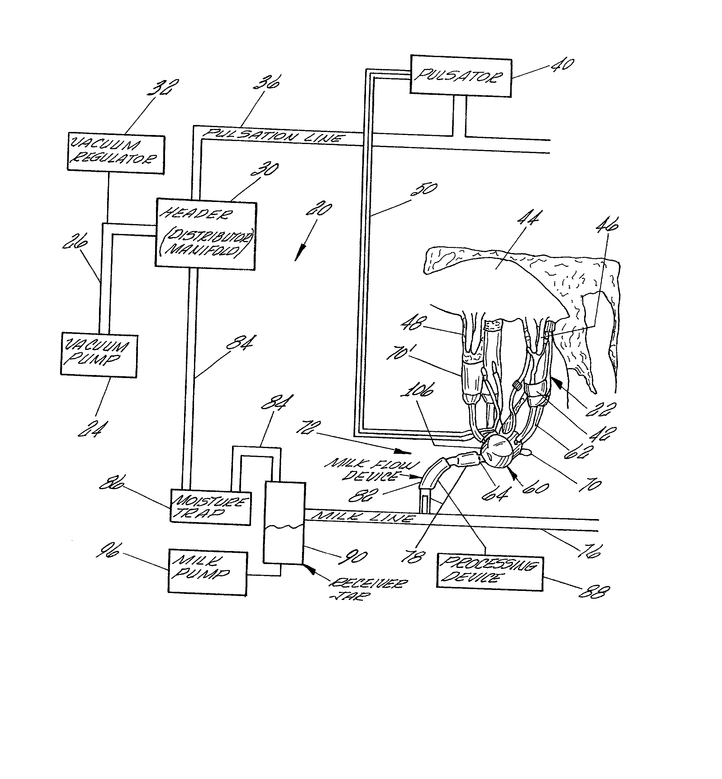
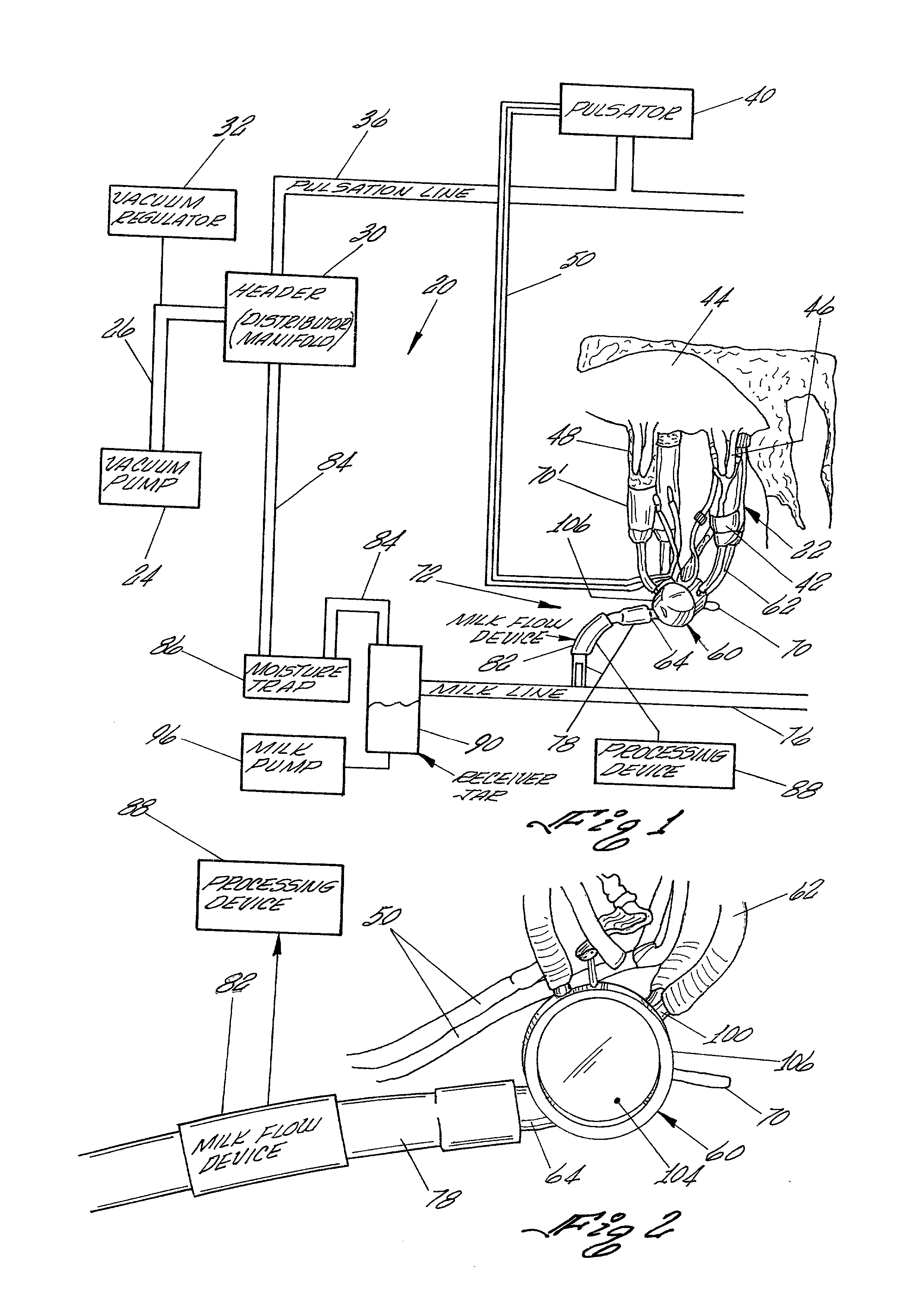
[0100] In order to explain the operation of the milking system 20 including a milk flow device 82 using the teachings of the present invention, the following operating example is provided.

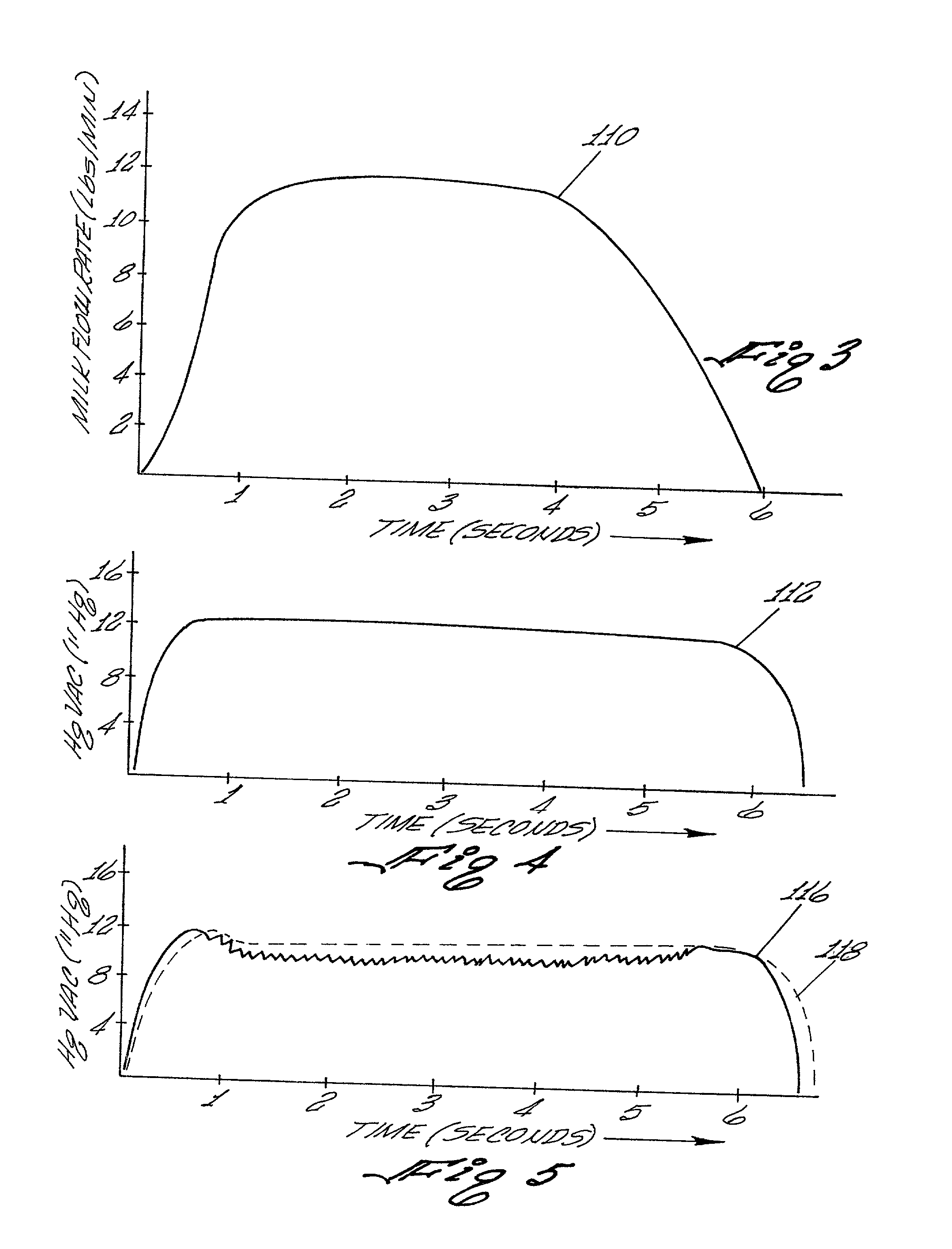
[0101] Typically, in a milking system 20, the preset vacuum level is established at approximately 12 inches Hg (12" Hg). A milking cycle of a cow to be milked using the present invention may be in the order of about 6 minutes. During the milking process, approximately 45 pounds of milk may be withdrawn from the cow. The relationship of pounds per minute for each minute of the milking cycle for the above example is as follows:

1TABLE 1 Pounds of Milk Cumulative Pounds of Minute of per Minute Milk Withdrawn Milking Cycle (lbs / min) During Milking Cycle Minute 1 5 5 Minute 2 through Minute 4 12 36 Minute 5 and Minute 6 Approximately 45 2.5

[0102] Referring now to the chart illustrated in FIG. 3, the chart plots as curve 110 the milk flow rate as function of time during the above described milking cycle o...


PUM


Abstract

A method for measuring flow rate of a continuous fluid flow is shown. The method comprises the steps of generating a first signal at a first predetermined location representing a height of a selected section of the continuous fluid flow at the first predetermined location and for generating a second signal at a second predetermined location located in a selected direction and a known distance representing that the selected section of the continuous fluid flow has traversed from the first predetermined location to the second predetermined location; generating a third signal representing the conductivity of the fluid; receiving the first signal, the second signal and the third signal and creating a data stream therefrom; calculating from the data stream an elapsed time for the selected section of the continuous fluid flow to traverse the known distance; calculating from the data stream an average conductivity of the fluid from the data stream; deriving the cross-sectional area of the selected section from the height of the selected section compensated for variance in conductivity; calculating the volume of fluid flow using the cross-sectional area and elapsed time; and generating an output signal representing the calculated volume of fluid flow.

Description

CROSS-REFERENCES TO RELATED APPLICATIONS[0001] Not Applicable[0002] Not ApplicableREFERENCE TO A "MICROFICHE APPENDIX" (SEE 37 CFR 1.96)[0003] Not Applicable[0004] 1. Field of the Invention[0005] This invention relates generally to a method for measuring flow rate of a continuous fluid flow, and specifically to a method measuring the flow rate of a substantially continuous milk flow in a milking system. The method comprises the steps of generating a first signal at a first predetermined location representing a height of a selected section of the continuous fluid flow at the first predetermined location and for generating a second signal at a second predetermined location located in a selected direction and known distance representing that the selected section of the continuous fluid flow has traversed from a first predetermined location to a second predetermined location, receiving a first signal and second signal and creating a data stream therefrom; calculating from the data strea...

Claims


Application Information

Patent Timeline
IPC IPC(8): A01J5/01
CPCA01J5/01
Inventor FEMATT, RAFAEL ANTONIO
Owner TECH HLDG
Why Eureka
Try Eureka