Image quality improvement for liquid crystal displays

a liquid crystal display and image quality technology, applied in the field of liquid crystal displays, can solve the problems of reducing the available contrast of the lcd, limiting the driving voltage, and increasing the severity of image degradation of small lcds and high driving voltages

Inactive Publication Date: 2002-09-26
SNAP INC +1
View PDF4 Cites 5 Cited by
  • Summary
  • Abstract
  • Description
  • Claims
  • Application Information

AI Technical Summary

Benefits of technology

[0045] A technical advantage of the present invention is improved image quality in microdisplays. Another technical advantage is in smoothing transitions between pixel voltages that generate strong fringe field effects. Other technical advantages of the present disclosure will be readily apparent to one skilled in the art from the following figures, descriptions, and claims. Various embodiments of the invention obtain only a subset of the advantages set forth. No one advantage is critical to the invention.
[0046] A more complete understanding of the present disclosure and advantages thereof may be acquired by referring to the following description taken in conjunction with the accompanying drawings, wherein:
[0047] FIG. 1 is a schematic plan view of a portion of a liquid crystal display;
[0048] FIG. 2 is a schematic elevational view of a portion of the liquid crystal display of FIG. 1;
[0049] FIG. 3 is a schematic block diagram of a liquid crystal display system;
[0050] FIG. 4 is a schematic diagram of a portion of the liquid crystal display of FIG. 3;

Problems solved by technology

A problem exists in small LCDs, especially microdisplays, which have small pixel cell areas compared to the area of the gaps between the pixel cells.
This leads to image degradation of increasing severity for small LCDs and high driving voltages.
Limiting the driving voltages helps, but reduces the available contrast of the LCD.

Method used


Image

  • Image quality improvement for liquid crystal displays
  • Image quality improvement for liquid crystal displays
  • Image quality improvement for liquid crystal displays

Examples


Embodiment Construction

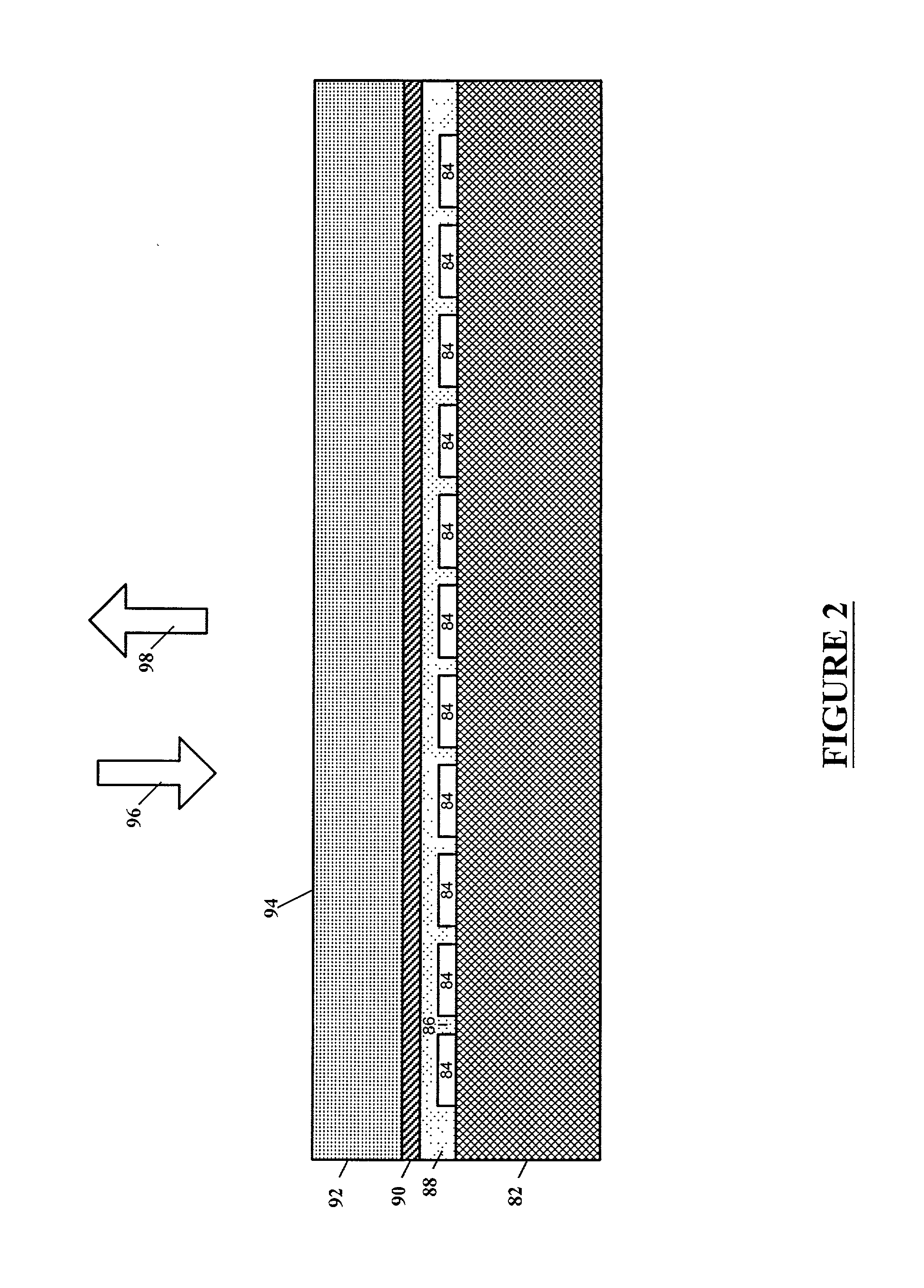
[0056] The present invention is directed to a liquid crystal display (LCD) comprising a matrix of liquid crystal pixels having light modifying properties controlled by voltage values stored in capacitors comprising the areas representing the pixels in the matrix of pixels of the LCD. A plurality of digital-to-analog converters (DACs) are coupled through analog switches to columns of the pixel matrix for voltage charging of the columns. Row analog switches connect each column to a desired respective pixel capacitor plate on a selected row, thereby transferring the voltage values on the columns to the respective pixel capacitors. The embodiments of the invention improve image quality of a liquid crystal display (LCD) by modifying the video voltage values written to the pixel capacitors in order to reduce the magnitude change of voltage transitions from one adjacent pixel area to another. If the voltage change transition between adjacent pixel areas is too large in magnitude, the volta...


PUM


Abstract

A liquid crystal display (LCD) system, comprising a matrix of pixels, analyzes a video data stream for grayscale level jumps from extreme black to moderate gray levels. Transitions in grayscale levels are restricted between adjacent pixels so as to reduce image degradation due to fringe field effects. A memory, such as a plurality of shift registers, may be used to store grayscale levels of adjacent pixels which are compared and if a ratio between these grayscale levels exceeds a desire value then at least one of the grayscale levels is modified.

Description

[0001] The application is related to co-pending application Ser. No. ______, entitled "Image Quality Improvement for Liquid Crystal Displays" by Matthias Pfeiffer, Terence R. Klein, Russell J. Flack and John Karl Waterman, filed ______, and is incorporated herein by reference for all purposes.[0002] The present invention relates generally to liquid crystal display (LCD) devices, and more particularly to a system, apparatus and method for improving image quality by limiting the difference between gray scale values of adjacent pixels.BACKGROUND OF THE INVENTION TECHNOLOGY[0003] Liquid crystal displays (LCDs) are commonly used in devices such as portable televisions, portable computers, control displays, and cellular phones to display information to a user. LCDs act in effect as a light valve, i.e., they allow transmission of light in one state, block the transmission of light in a second state, and some include several intermediate stages for partial transmission. When used as a high ...

Claims


Application Information

Patent Timeline
Patent Type & Authority Applications(United States)
IPC IPC(8): G09G3/20G09G3/36
CPCG09G3/2011G09G3/3611G09G3/3648G09G2310/027G09G2320/02G09G2320/0209G09G2340/145G09G3/36
Inventor PFEIFFER, MATTHIASKLEIN, TERENCE R.FLACK, RUSSELL JAMESWATERMAN, JOHN KARL
Owner SNAP INC
Why Eureka
Try Eureka