Neuro-thrombectomy catheter and method of use

Inactive Publication Date: 2002-09-19
SHADDUCK JOHN H
View PDF6 Cites 206 Cited by
  • Summary
  • Abstract
  • Description
  • Claims
  • Application Information

AI Technical Summary

Benefits of technology

[0011] More in particular, the microcatheter of the invention is provided with an extraction channel that carries a series of high-intensity pressure-creating emitters along the entire length of the channel for creating brief, intense energy differentials along the entire extraction channel. An energy source, such as a laser and a computer controller, or Rf electrodes, are used to deliver pulsed energy to the emitters (i) to create a sequence of pressure differentials to create peristaltic fluid flows in the extraction channel to suction thromboemboli from the targeted site and entrain emboli within the fluid flows, and (ii) to emulsify and ablate thromboemboli along the entire length of the microchannel to prevent clogging of the channel. By this means of operation, the extraction channel can be very small in cross section, for example from 0.1 mm to 1.5 mm.
[0013] The fluid flow in the extraction channel caused by the sequential energy deliveries causes suction forces at the distal open terminus of the extraction channel that draws thrombus and emboli into the channel. Of particular interest, the plurality of emitters are closely spaced in the distal region of the extraction channel to apply energy to occlusive materials then entrained in the fluid flow within the extraction channel. The emitters then ablate and fragment such thrombus and emboli multiple times until the extraction channel widens, thus eliminating the chance of emboli clogging the very small dimension channel.

Problems solved by technology

This sudden blockage is an embolism.
Current mechanical interventions can be relatively invasive and are limited in their accessibility to larger vessels.
Thrombolytic therapy may be effective but thrombolytics are not indicated for all stroke victims, are not effective on all thrombus.
Further, thrombolytic therapy has associated risks, some of which may have severe consequences-particularly hemorrhage.

Method used


Image

  • Neuro-thrombectomy catheter and method of use
  • Neuro-thrombectomy catheter and method of use
  • Neuro-thrombectomy catheter and method of use

Examples


Embodiment Construction

[0039] 1. Type "A" Neuro-Thrombectomy Catheter System.

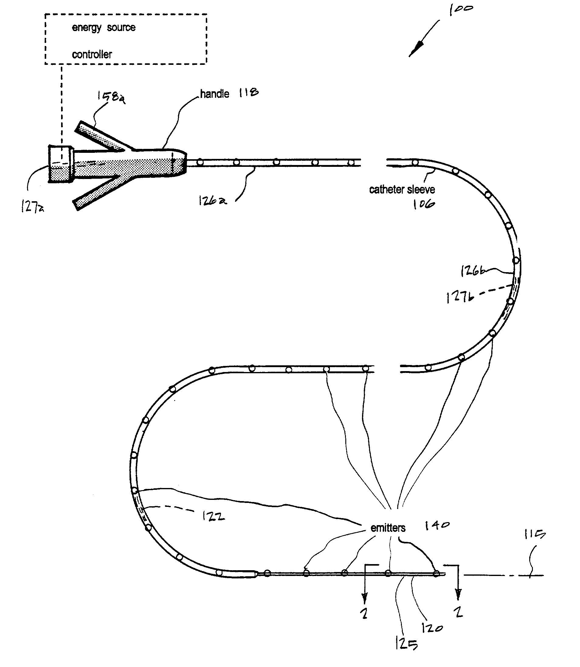
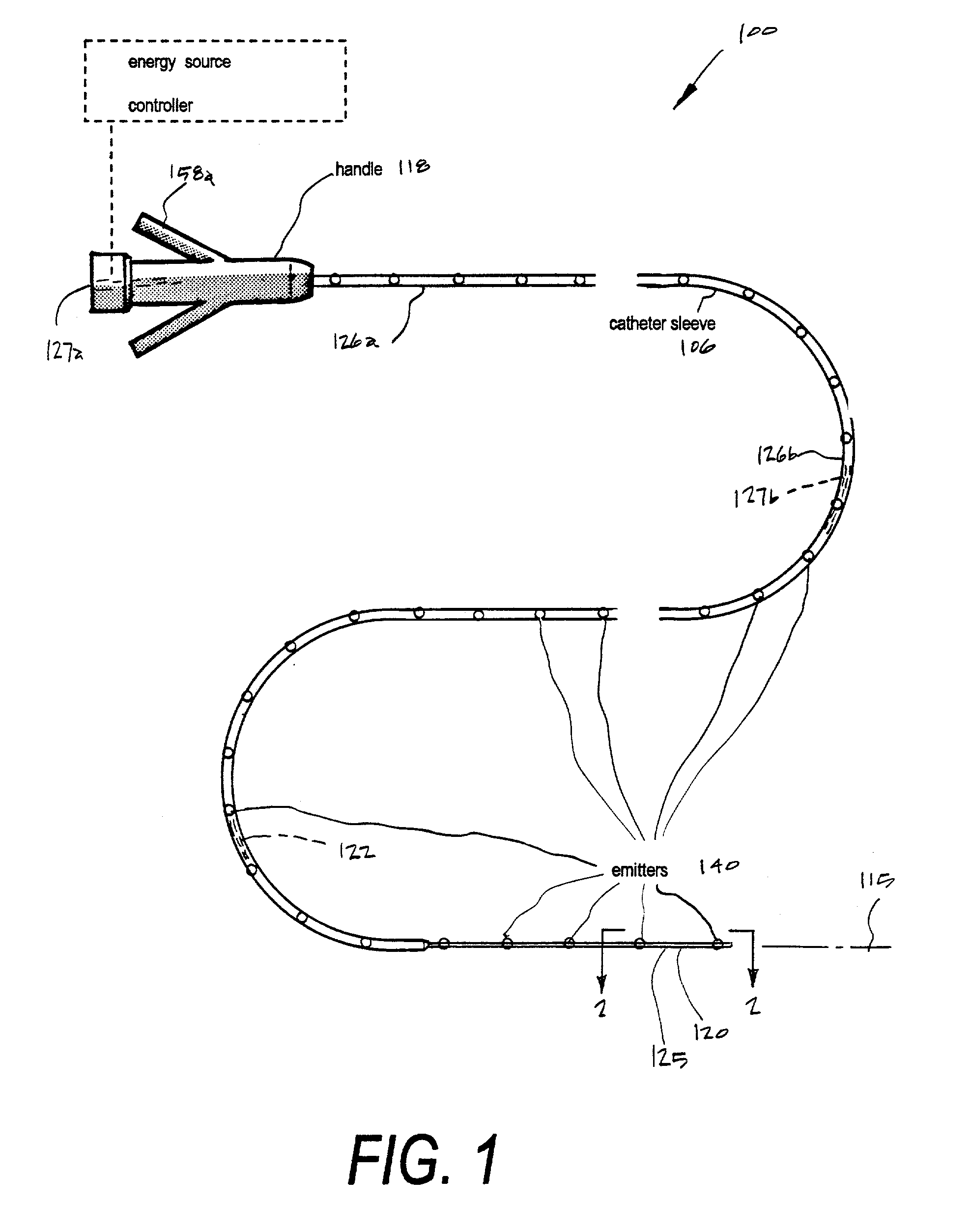
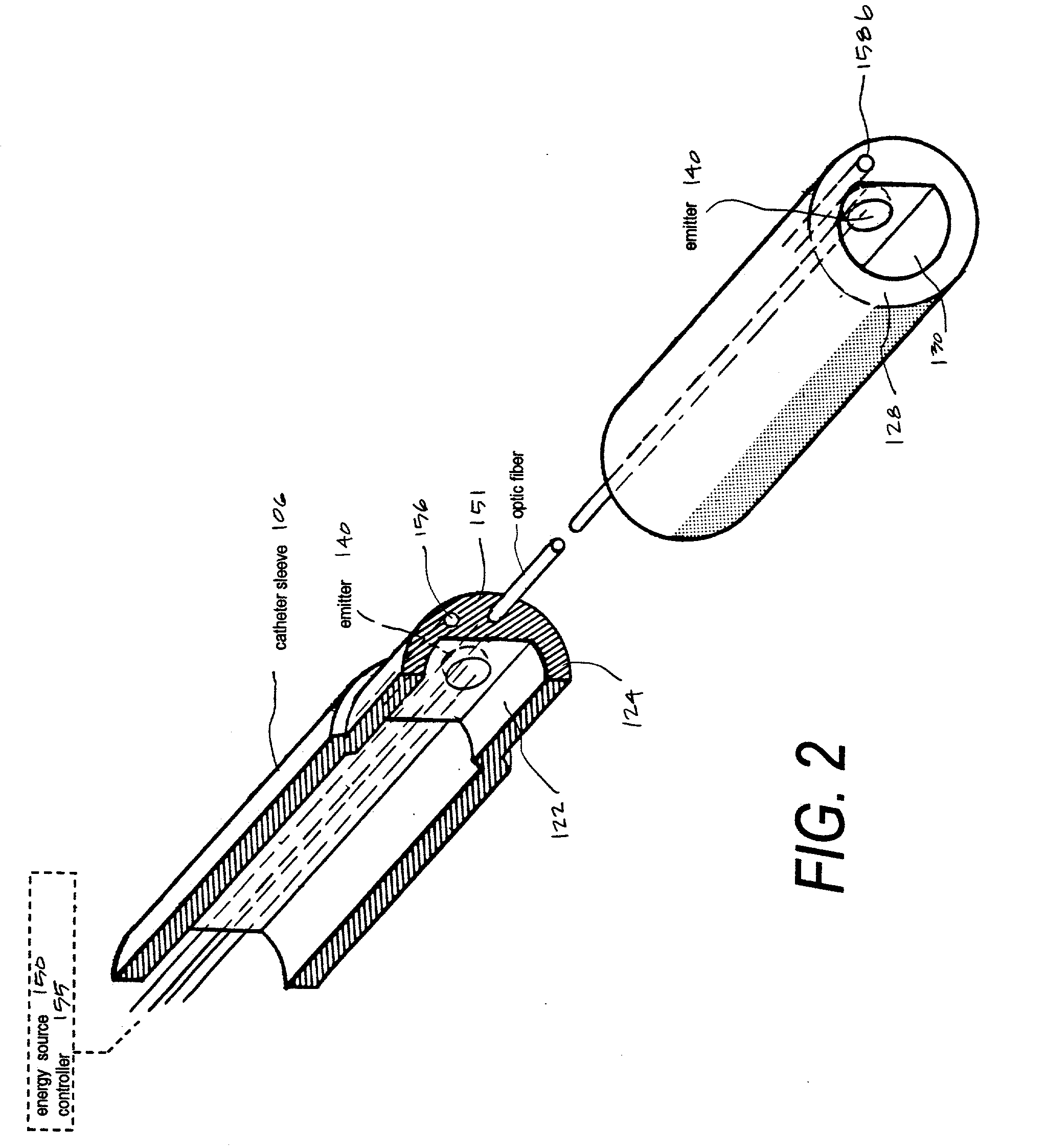
[0040] Referring to FIGS. 1 & 2, a Type "A" microcatheter system 100 corresponding to the invention is shown having a thin-wall catheter body or sleeve member 106 that extends along axis 115 from a proximal handle or manifold 118 to distal working end 120 with interior extraction lumen or microchannel 122 extending therethrough. The microcatheter sleeve is fabricated utilizing technology known in the art to provide catheter walls 124 with predetermined flexibility characteristics that can allow precise intravascular navigation, pushability and trackability.

[0041] The microcatheter of the invention defines a distal sleeve portion 125 that can have a much smaller cross section than currently available catheters for accessing a targeted neuro-thrombectomy site--while still providing extraction (fluid suction) channel functionality. The exemplary microcatheter of FIG. 1 is adapted for navigating cerebral vasculature with distal sleev...


PUM


Abstract

A microcatheter for removing thromboemboli from cerebral arteries in patients suffering from ischemic stroke. The microcatheter provides an extraction lumen that can be scaled to a very small diameter that is still capable of extracting and emulsifying thrombus without clogging the channel. The microcatheter of the invention uses a series of spaced apart energy application mechanisms along the entire length of the catheter's extraction lumen to develop sequential pressure differentials to cause fluid flows by means of cavitation, and to contemporaneously ablate embolic materials drawn through the extraction lumen by cavitation to thereby preventing clogging of the lumen. The catheter system thus provides a functional high-pressure extraction lumen that is far smaller than prior art catheter systems. Preferred mechanisms for energy delivery are (i) a laser source and controller coupled to optic fibers in the catheter wall or (ii) an Rf source coupled to paired electrodes within the extraction lumen. Each energy emitter can apply energy to fluid media in the extraction channel of the catheter-wherein the intense energy pulses can be sequentially timed to cause fluid media flows in the proximal direction in the channel.

Description

[0001] This application claims priority from Provisional U.S. Patent Application Ser. No. 60 / 277,068 filed Mar. 19, 2001 (Docket No. S-AZUR-002) having the same title as this disclosure, which is incorporated herein by reference.[0002] 1. Field of the Invention[0003] The present invention relates to medical devices and techniques, and more particularly to a type of catheter that can be scaled to very small diameters suitable for the removal of occlusive thromboemboli in ischemic stroke patients. More in particular, the microcatheter of the invention provides a series of energy delivery structures along the entire length of the catheter's extraction lumen (i) to develop sequential high pressure differentials to cause suction at the distal catheter terminus and fluid flows within the lumen, and (ii) to contemporaneously ablate thromboemboli drawn through the very small extraction lumen to preventing clogging thus providing a functional high-pressure thromboemboli extraction lumen that...

Claims


Application Information

Patent Timeline
IPC IPC(8): A61B17/00A61B17/22A61B18/14A61B18/22A61N1/06
CPCA61B17/22A61B18/1492A61B18/22A61B2017/00172A61B2018/1417A61B2018/1472A61N1/06A61B18/245A61B18/24A61B18/1815A61B18/18
Inventor SHADDUCK, JOHN H.
Owner SHADDUCK JOHN H
Why Eureka
Try Eureka