
Paper feeder for an image forming apparatus

Inactive Publication Date: 2002-09-19
SHARP KK
View PDF5 Cites 19 Cited by
  • Summary
  • Abstract
  • Description
  • Claims
  • Application Information

AI Technical Summary

Benefits of technology

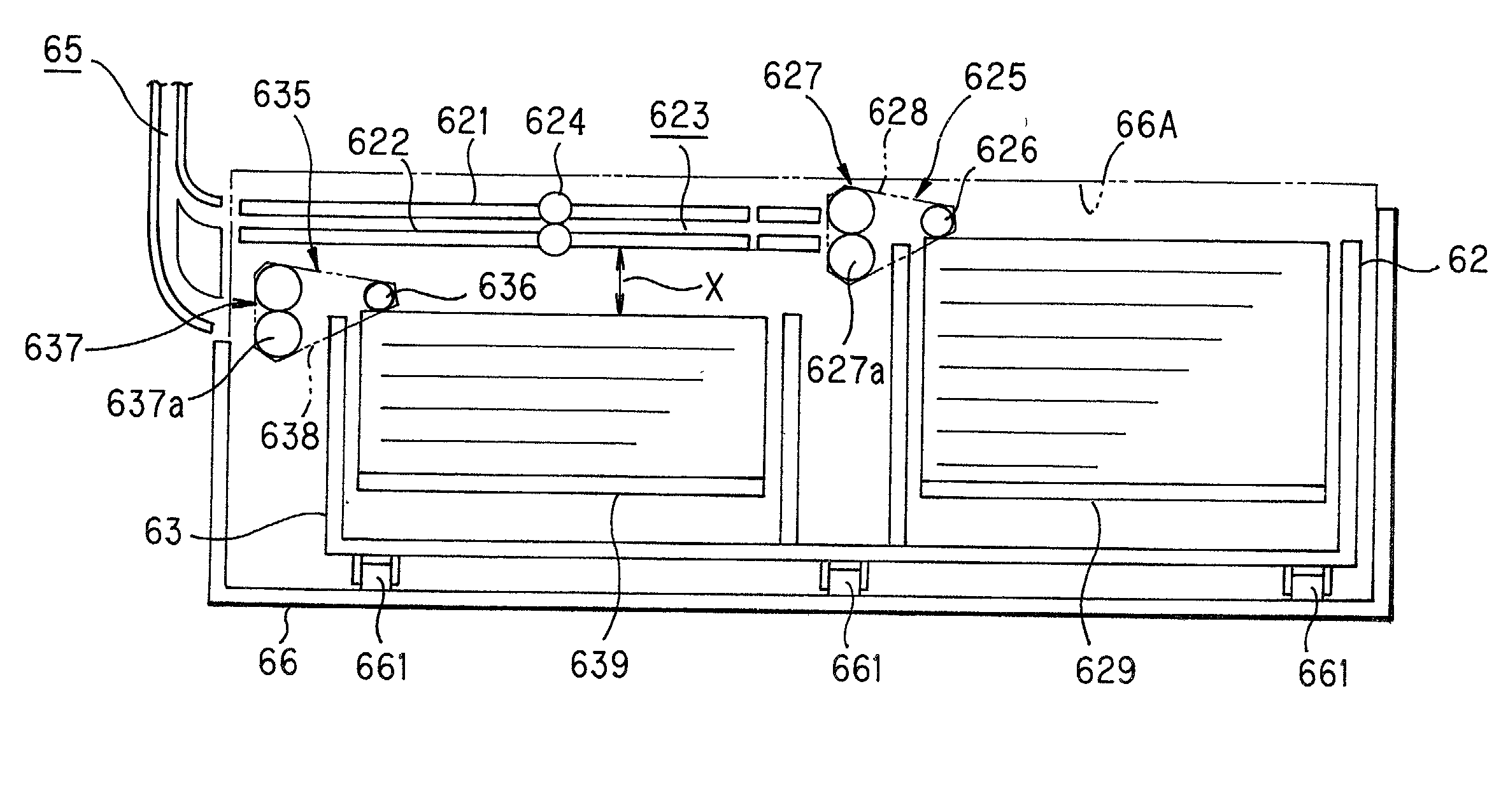
[0009] The present invention has been devised in view of the above problems and it is therefore an object of the present invention to provide improvement in the operativity of paper loading in to each cassette of the paper feeder having multiple paper feed cassettes which are arranged abreast along the sheet feed direction at the same level.

Problems solved by technology

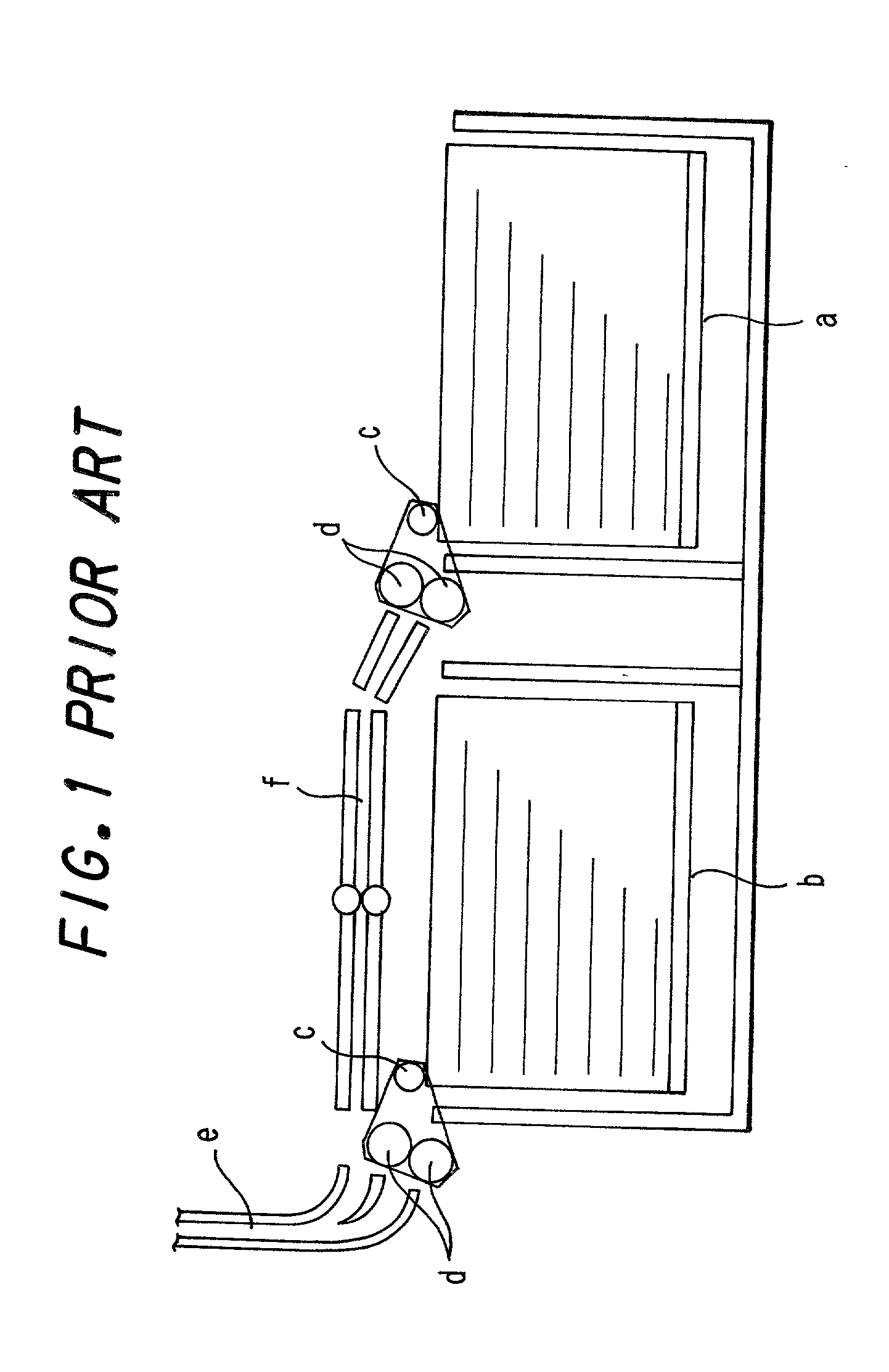
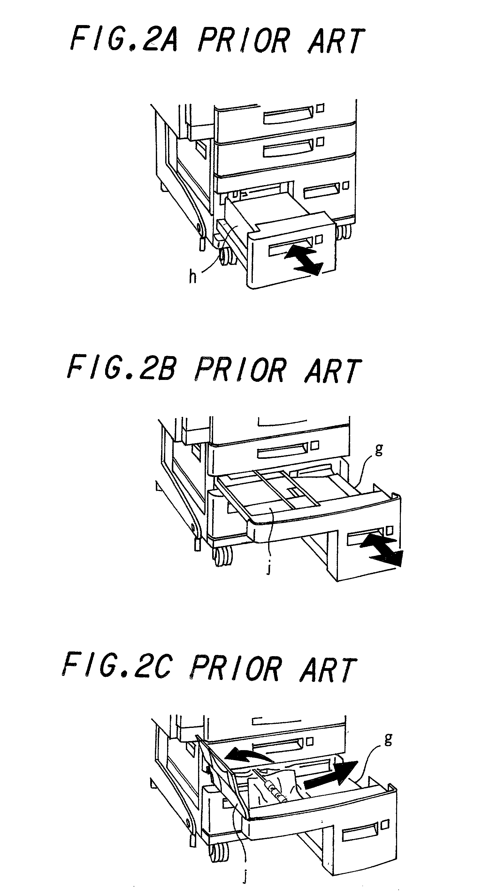
Though there has been a demand for paper loading to be done at the same time for both the paper feed cassettes, each paper feed cassette has to be drawn out individually, so that the task of paper loading has been complicated and time-consuming.

Method used


Image

  • Paper feeder for an image forming apparatus
  • Paper feeder for an image forming apparatus
  • Paper feeder for an image forming apparatus

Examples


Embodiment Construction

[0046] The embodiment of the present invention will hereinafter be described in detail with reference to the accompanying drawings.

[0047] FIG. 3 is a schematic structural view showing the interior of an image forming apparatus 1 according to this embodiment. This image forming apparatus 1 is a multifunctional type having the functions of a copier, printing machine and facsimile machine combined. This image forming apparatus 1 comprises a printer 2, scanner 3, automatic document feeder 4, paper discharge unit 5 and multi-layered paper feeder 6. The configuration of each part will be described next.

[0048] Automatic document feeder 4 has a document feeder mechanism 41, by which documents set on a document set tray 40 are successively fed to and positioned on a glass platen 30 so that the image of each document is scanned by scanner 3 and then conveyed and discharged to a document output tray 42. Further, in order to allow a document incapable of being fed to be placed on glass platen 3...


PUM


Abstract

A paper feeder includes: a multiple number of paper feed cassettes arranged abreast at approximately the same level in the sheet feed direction. These paper feed cassettes are formed into a unibody structure so that they can be pulled out altogether. The more upstream a paper feed cassette is located with respect to the sheet feed direction, the higher the level of the upper surface of the paper feed cassette is arranged. This arrangement affords a space over the downstream paper feed cassette, in which a feed path for recording paper picked up from a paper feed cassette located on the upstream side can be arranged.

Description

BACKGROUND OF THE INVENTION[0001] (1) Field of the Invention[0002] The present invention relates to a paper feeder built in an image forming apparatus such as a copier, printer, facsimile machine or the like. In particular, the present invention relates to an improvement of a paper feeder having a multiple number of paper feed cassettes arranged abreast at the same level.[0003] (2) Description of the Prior Art[0004] Conventionally, with concern to image forming apparatus such as copiers, printers facsimile machines and multifunctional machines consisting of these, there has been a demand of reducing the footprint of the apparatus to as small as possible. To meet this demand, so-called vertical feed type image forming apparatus have become widespread, in which paper is fed from the paper feed cassette arranged at the bottom of the image forming apparatus and conveyed along the paper feed path laid out vertically to the paper output tray located at the top.[0005] Concerning the image ...

Claims


Application Information

Patent Timeline
IPC IPC(8): B65H5/38B65H1/26B65H1/28B65H3/00B65H3/06B65H3/44B65H5/06
CPCB65H1/266B65H1/28B65H5/062B65H2404/1442B65H2405/32B65H2601/11B65H2601/325
Inventor OKADA, NAOFUMIHAYASHI, SHIGEKINANBA, TOYOAKINAGATA, JINICHIOGITA, TOSHIKITOKISHIGE, KIYOSHI
Owner SHARP KK
Learn More