
Winding method and device for photo film and photo film carrier

a technology of photo film and winding device, which is applied in the direction of printing, instruments, transportation and packaging, etc., can solve the problems of uneven rewinding of photo film to the photo film cassette, photo film is likely to have scratches, flexing, other damage, and the surface of the photo film is rubbed by one another,

Inactive Publication Date: 2002-09-19
FUJIFILM CORP +1
View PDF0 Cites 21 Cited by
  • Summary
  • Abstract
  • Description
  • Claims
  • Application Information

AI Technical Summary

Benefits of technology

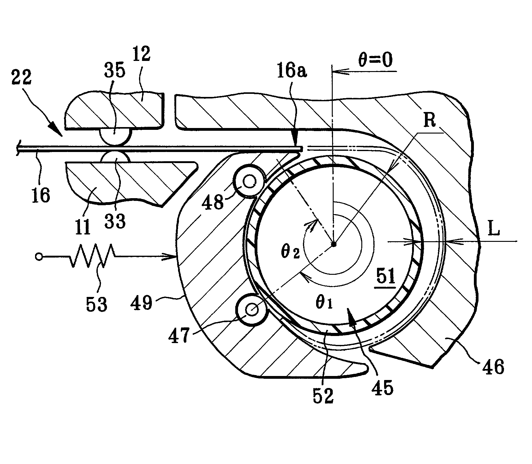
[0008] In order to achieve the above and other objects and advantages of this invention, a winding method for photo film is provided, in which the photo film is introduced to a winder shaft through a feeding path. A leading end of the photo film is tightly fitted on the winder shaft by pressing the photo film from the feeding path, to prevent the leading end from being loose at the winder shaft when a second turn portion of the photo film comes to contact the leading end after substantially one rotation of the leading end.
[0009] Also, a winding device for photo film is provided, and includes a rotatable winder shaft. A feeding path introduces the photo film to the winder shaft. A leading end guide plate is curved in an arc shape at a predetermined interval to the winder shaft, for receiving a leading end of the photo film having reached the winder shaft from the feeding path, to guide the photo film toward the winder shaft by bending in an arc shape. A tightening guide mechanism is curved in an arc shape, for tightly fitting the leading end on the winder shaft by pressing the photo film from the leading end guide plate, to prevent the leading end from being loose at the winder shaft when a second turn portion of the photo film comes to contact the leading end after substantially one rotation of the leading end.
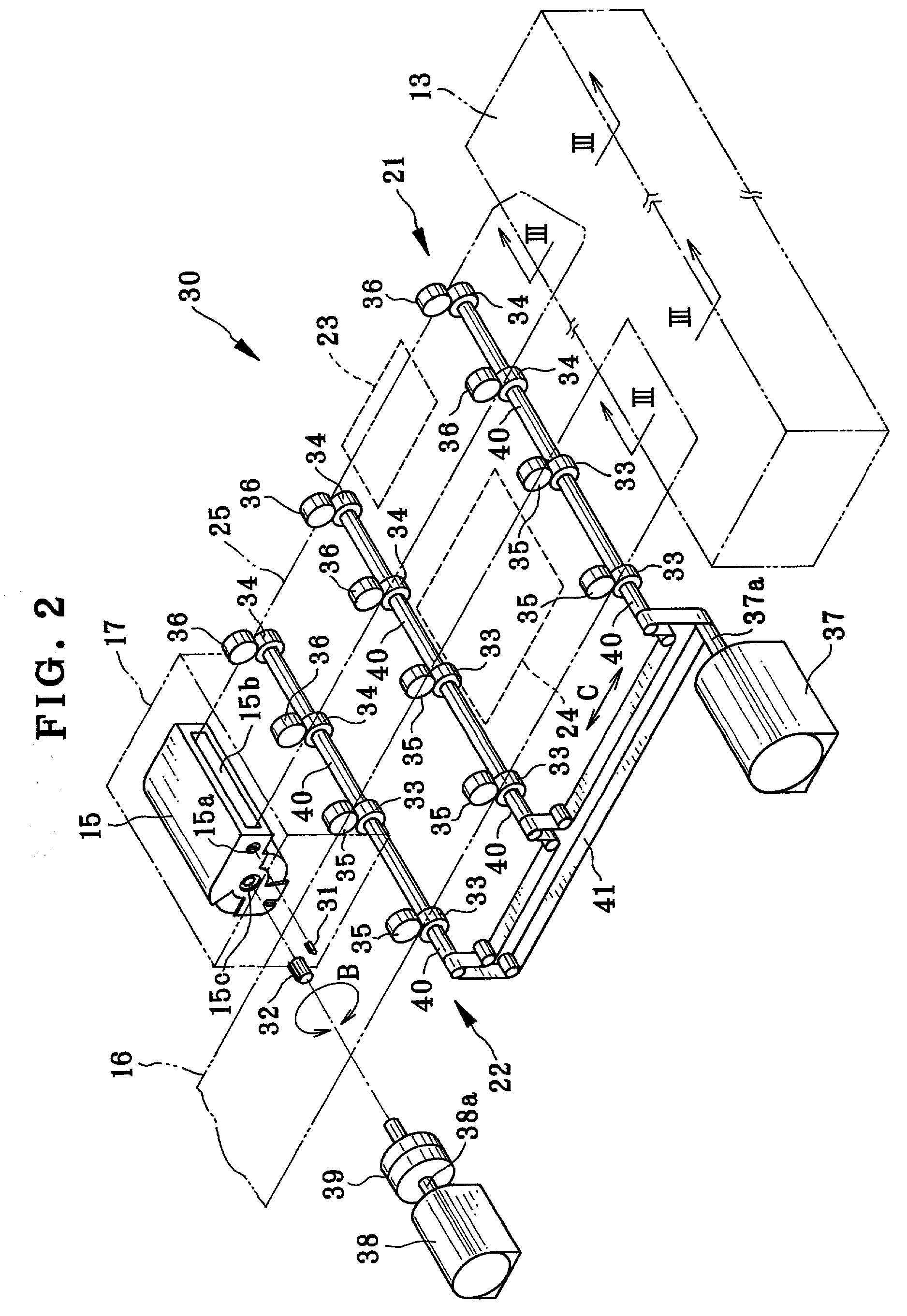
[0010] Furthermore, a feeding mechanism feeds the photo film at a predetermined introducing speed V1 through the feeding path. A shaft drive mechanism rotates the winder shaft in a winding direction at a predetermined circumferential speed V2 higher than the introducing speed V1, whereby the guiding mechanism eliminates looseness from the leading end.
[0018] According to another aspect of the invention, a photo film carrier adapted for reading or printing an image frame in photo film is provided. The photo film carrier includes a loader unit for being loaded with the photo film, a winder unit for winding the photo film from the loader unit, a feeding path for passing the photo film from the loader unit to the winder unit, and an opening, formed in the feeding path, for external access to the photo film for reading or printing of the image frame. In the photo film carrier, the winder unit includes a rotatable winder shaft. A leading end guide plate is curved in an arc shape at a predetermined interval to the winder shaft, for receiving a leading end of the photo film having reached the winder shaft from the feeding path, to guide the photo film toward the winder shaft by bending in an arc shape. A tightening guide mechanism is curved in an arc shape, for tightly fitting the leading end on the winder shaft by pressing the photo film from the leading end guide plate, to prevent the leading end from being loose at the winder shaft when a second turn portion of the photo film comes to contact the leading end after substantially one rotation of the leading end.

Problems solved by technology

Failure in smooth rewinding to the photo film cassette is likely to occur after printing operation with the photo film.
The photo film is likely to have scratches, flexing, and other damages.
However, the photo film carrier of the prior art has a problem in that at least one turn of the photo film must be wound about the winder shaft before the turn of the photo film can be tightened.
Surfaces of the photo film are rubbed by one another, and scratched or damaged.
This problem is typically serious if the photo film is 135 type, because the photo film does not have a leader but has the image frame starting directly from a front end of the photo film.

Method used


Image

  • Winding method and device for photo film and photo film carrier
  • Winding method and device for photo film and photo film carrier
  • Winding method and device for photo film and photo film carrier

Examples


Embodiment Construction

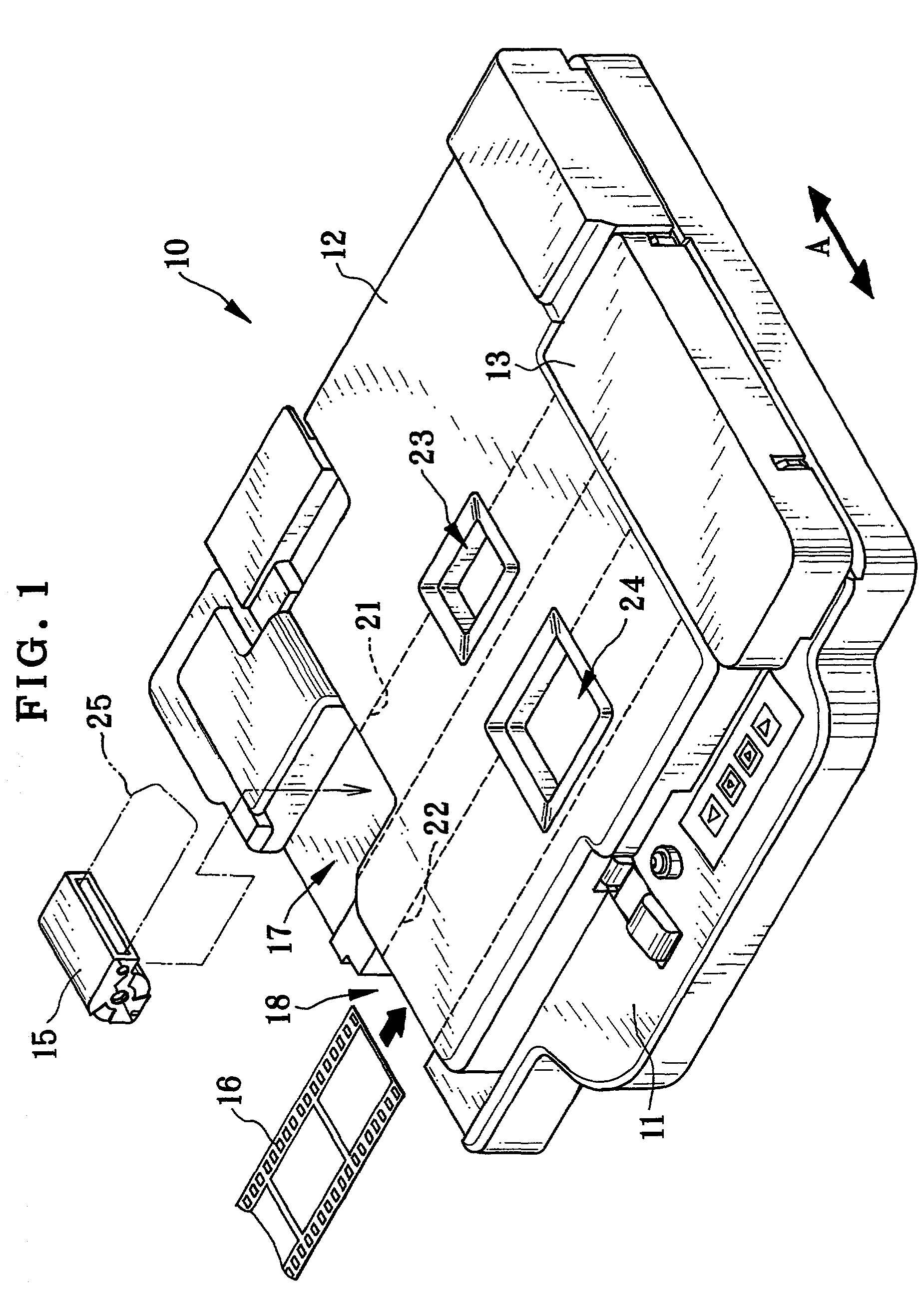
[0025] In FIG. 1, a photo film carrier or holder 10 of the invention is illustrated. The photo film carrier 10 is used in a printer / processor (not shown), which is a machine constituted by a printer section and a processor section, for producing photographic prints. In the printer / processor, image frames are printed to photographic paper by use of developed photo film. Then the photographic paper is subjected to development, bleaching and fixation, rinsing and drying before prints are obtained.

[0026] The photo film carrier 10 includes a base plate 11, a cover 12, a winder unit 13 and the like. The photo film carrier 10 is used with either desired one of photo film cassette 15 of the IX240 type and photo film 16 of 135 type. The photo film carrier 10 includes a cassette loader unit 17 and a photo film loader unit 18. The cassette loader unit 17 is loadable with the photo film cassette 15 of the IX240 type. The photo film loader unit 18 is loadable with the photo film 16 of 135 type.

[...


PUM


Abstract

In a photo film carrier for use with a photographic printer, a winding device includes a rotatable winder shaft for photo film. A feeding path introduces the photo film to the winder shaft. A leading end guide plate is curved in an arc shape at a predetermined interval L to the winder shaft, for receiving a leading end of the photo film having reached the winder shaft from the feeding path, to guide the photo film toward the winder shaft in an arc shape. A tightening guide mechanism is curved in an arc shape, for tightly fitting a leading end on the winder shaft by pressing the photo film from the feeding path, to prevent the leading end from being loose at the winder shaft when a second turn portion of the photo film comes to contact the leading end after substantially one rotation of the leading end.

Description

[0001] 1. Field of the Invention[0002] The present invention relates to a winding method and device for photo film and a photo film carrier. More particularly, the present invention relates to a winding method and device for photo film, and a photo film carrier in which the photo film can be prevented from being scratched or damaged.[0003] 2. Description Related to the Prior Art[0004] There is a photo film cassette of the IX240 type which contains a roll of photo film, such as negative photo film. After the photo film is developed, the photo film is wound back on a cassette spool the photo film cassette, and accommodated in the photo film cassette. To print an image frame in the photo film to photographic paper, thermosensitive recording material or the like, a photo film carrier is used for setting the photo film cassette, from which the photo film is drawn out in the photo film carrier. The photo film from the photo film cassette is fed intermittently, to set the image frame in a ...

Claims


Application Information

Patent Timeline
Patent Type & Authority Applications(United States)
IPC IPC(8): G03B27/62G03B27/58
CPCG03B27/587G03B27/6285
Inventor YAMASAKI, KAZUKI
Owner FUJIFILM CORP
Learn More