
Waterproof connector and method of inserting terminals in waterproof connector

a technology of waterproof connectors and terminals, which is applied in the direction of securing/insulating coupling contact members, line/current collector details, coupling device connections, etc., can solve the problems of prone to damage, terminals 105 and wires 104 cannot be easily inserted, etc., and achieve the effect of smooth passing

Inactive Publication Date: 2002-09-12
YAZAKI CORP
View PDF0 Cites 46 Cited by
  • Summary
  • Abstract
  • Description
  • Claims
  • Application Information

AI Technical Summary

Benefits of technology

[0005] It is therefore an object of this invention to provide a waterproof connector in which when inserting terminals in a mat seal (seal member), the mat seal is prevented from being twisted or deformed by the terminals.
[0006] Another object of the invention is to provide a terminal inserting method in which when inserting terminals in a mat seal, the terminals are prevented from being caught by the mat seal, thereby preventing the terminals from being damaged.
[0021] According to the invention, the mat seal can be provisionally retained by the distal end portions of the housing-side intimate-contact ribs and the distal end portions of the holder-side intimate-contact ribs, without causing the torsion and deformation of the mat seal, and therefore the metal terminals and the wires can be smoothly passed through the respective wire insertion holes, and the metal terminals can be positively inserted respectively into the terminal receiving chambers in the connector housing. As a result, when inserting the terminals into the mat seal, the terminals will not be caught by the mat seal, thereby preventing the terminals from being damaged.

Problems solved by technology

Therefore, there has been encountered a problem that the terminals 105 and the wires 104 can not be easily inserted into the terminal / wire press-fitting holes 102B when the seal member 102 is twisted or deformed.
Therefore, there has been encountered a problem that the ability of inserting the terminals 105 and wires 104 is adversely affected by the torsion or the like of this seal member, and the terminals 105 are liable to be caught by the seal member during the insertion, and therefore are liable to be damaged.

Method used


Image

  • Waterproof connector and method of inserting terminals in waterproof connector
  • Waterproof connector and method of inserting terminals in waterproof connector
  • Waterproof connector and method of inserting terminals in waterproof connector

Examples


Embodiment Construction

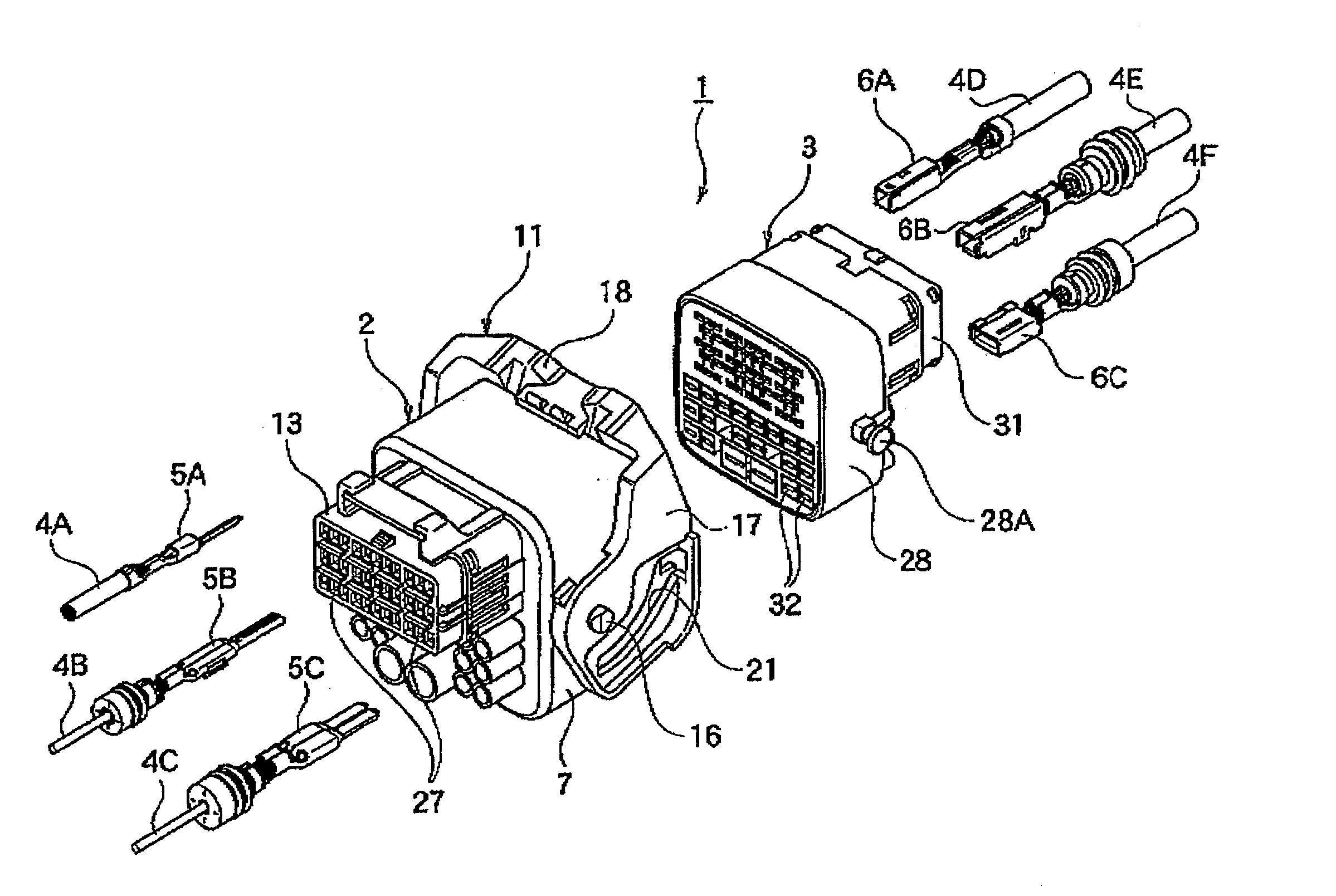
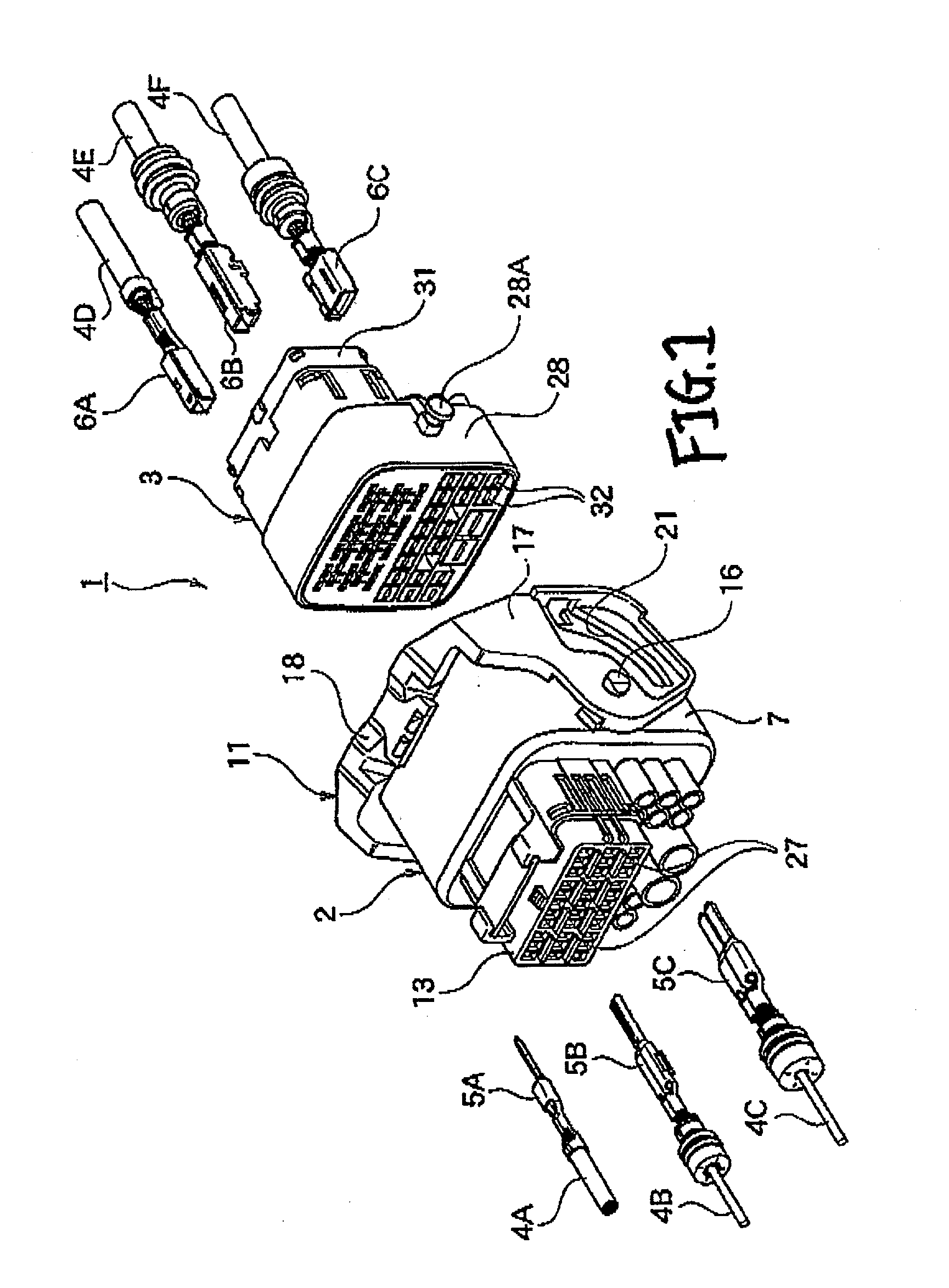
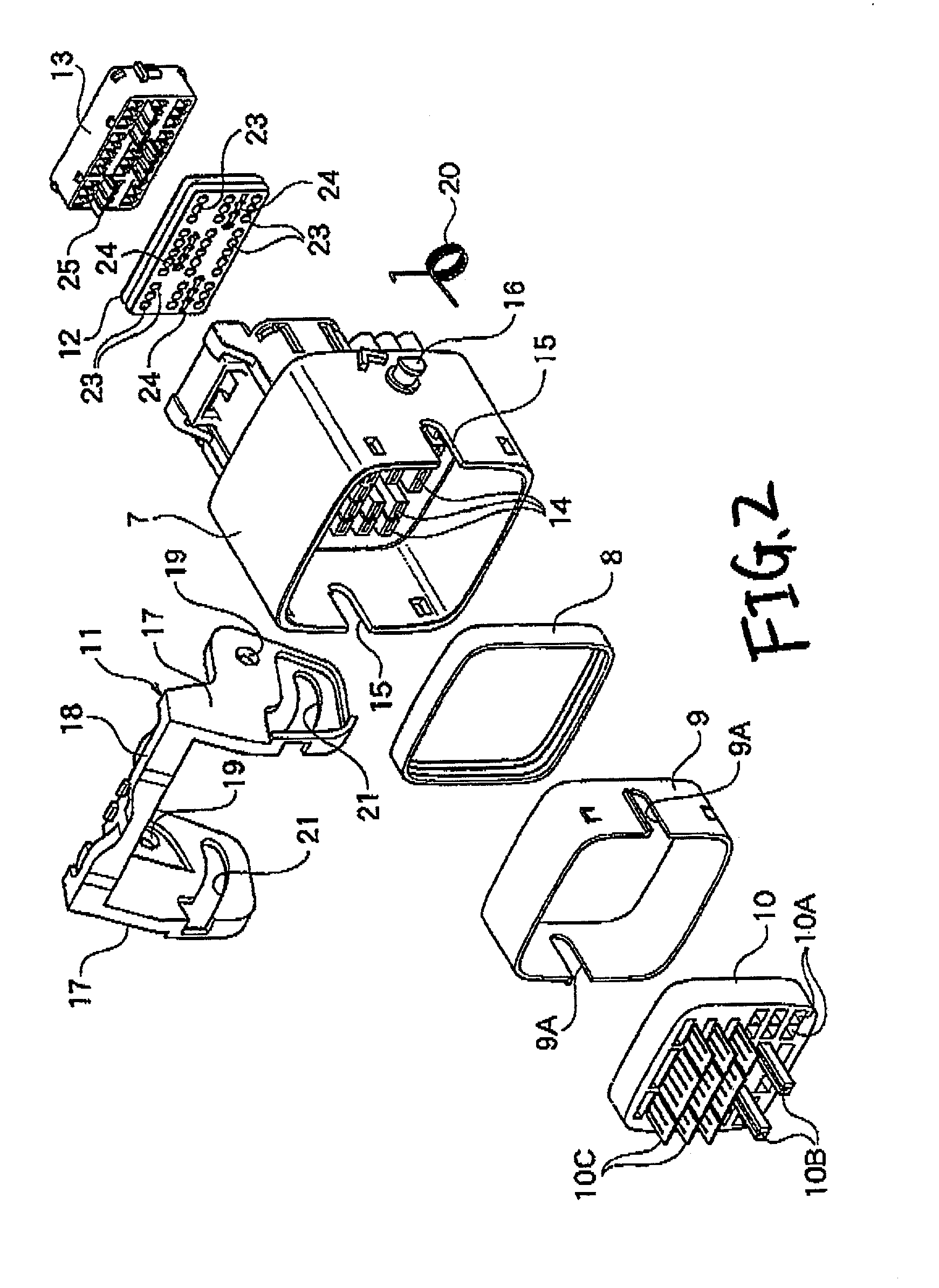
[0032] A preferred embodiment of a waterproof connector of the present invention, as well as a method of inserting terminals in the waterproof connector, will be described in detail with reference to the drawings. Although this embodiment described below is an example in which the invention is applied to a male and a female connector of a lever fitting-type connector, the invention can be applied to various connectors other than such a lever fitting-type connector.

[0033] Waterproof Connector

[0034] As shown in FIG. 1, the waterproof connector 1 according to the embodiment comprises a male connector 2 and a female connector 3 which can be connected together by fitting them together. As shown in FIG. 1, various male metal terminals 5A, 5B and 5C are secured respectively to ends of a plurality of wires 4A, 4B and 4C which are to be mounted in the male connector 2. On the other hand, various female metal terminals 6A, 6B and 6C are secured respectively to ends of a plurality of wires 4D,...


PUM


Abstract

Housing-side intimate contact ribs are formed on a rear end surface of a male connector housing (7), and a holder-side intimate-contact ribs (25) are formed on a mat seal holder 13 which holds a mat seal (12) on the male connector housing (7). These intimate-contact ribs are inserted respectively in inlet portions of intimate-contact cavity portions (24, 26) formed in the mat seal (12), thereby provisionally retaining the mat seal (12). In this condition, metal terminals can be easily and positively passed respectively through wire insertion holes (23) in the mat seal (12).

Description

BACKGROUND OF THE INVENTION[0001] This invention relates to a waterproof connector, and more particularly to a waterproof connector and a method of inserting terminals in the waterproof connector, in which the efficiency of an operation for mounting the terminals in a connector housing is enhanced.[0002] One known waterproof connector of this type is disclosed in JP-A-11-354196, and is shown in FIGS. 10A and 10B. As shown in FIG. 10A, the waterproof connector comprises a connector housing 101, a seal member 102 made of an elastic soft material, and a holder 103. The waterproof connector holds terminals 105 each connected to an end of a wire 104 therein. In this waterproof connector, when the holder 103 is locked to the connector housing 101, projections 103A (shown in FIG. 10B) on the holder 103 are press-fitted respectively into slit-shaped grooves 102A in the seal member 102 to expand the seal member 102 outwardly, so that the wires 104, press-fitted respectively in terminal / wire ...

Claims


Application Information

Patent Timeline
Patent Type & Authority Applications(United States)
IPC IPC(8): H01R13/52H01R43/00
CPCH01R13/5208H01R13/6278H01R43/005H01R13/62938
Inventor HAMAI, TSUYOSHIKUDO, TOSHIHARUKANDA, MASAHIRO
Owner YAZAKI CORP
Learn More