
Method for the sizing of a deterministic type packet-switching transmission network

a transmission network and packet-switching technology, applied in the direction of data switching networks, digital transmission, electrical equipment, etc., can solve the problems of disturbance or jitter increase, and insufficient deterministic nature of packet-switching transmission networks

Active Publication Date: 2002-09-05
THALES SA
View PDF7 Cites 16 Cited by
  • Summary
  • Abstract
  • Description
  • Claims
  • Application Information

AI Technical Summary

Benefits of technology

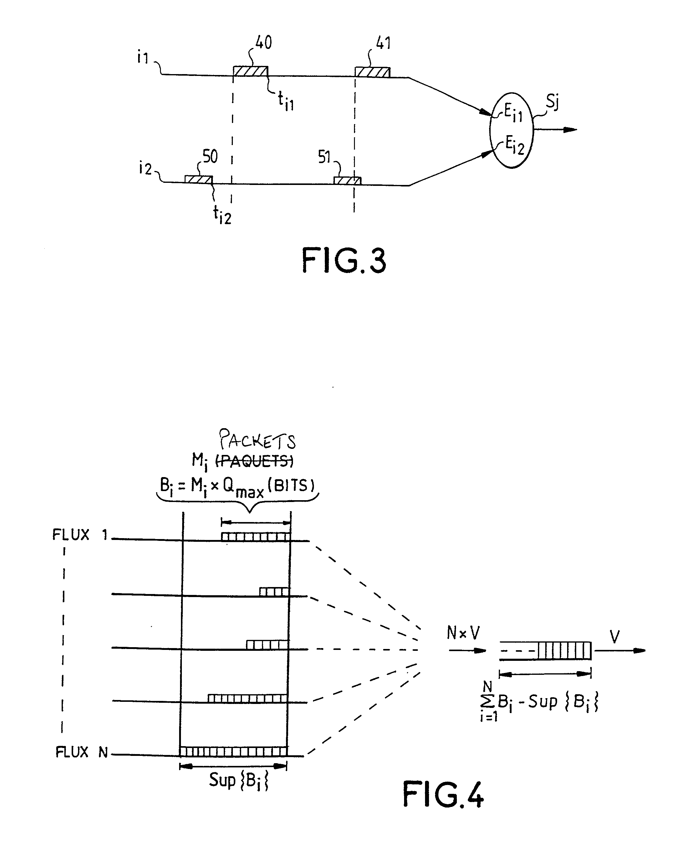
[0028] are sufficient to prevent any problem of congestion of the queues caused by bursts excessively close to each other, i.e. they meet either the inequality: 5 T ( M - 1 ) q max V

Problems solved by technology

However, it is not enough for the packet-switching transmission network to be deterministic in order to ensure its reliability.
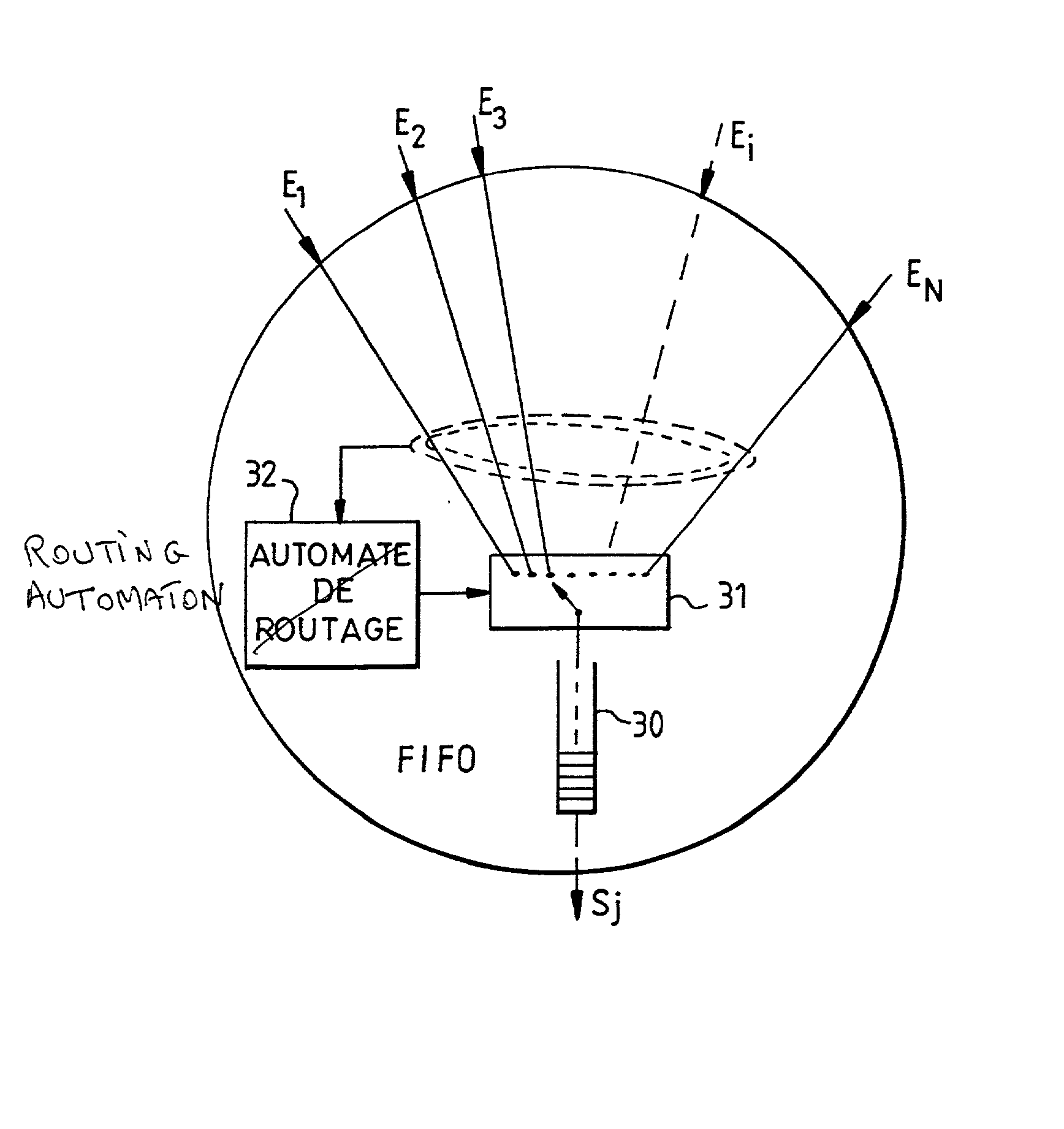
The problem of the congestion of an interconnection node brings us to that of the management of the queues, namely the occupancy rates and the risks of overflow of the FIFO memories positioned directly on output ports of the interconnection node.
The topology of the network is revised so long as this verification does not give satisfactory results.
However, as soon as they pass through a first interconnection node, they enter into competition with packets belonging to other information flows following other virtual paths and may therefore be forced to wait in queues at the output port that they have to take.
Such a passage through a queue disturbs the regularity of the initial bit rate of the packets.
This disturbance or jitter increases with the connection nodes crossed and may ultimately give rise to packet aggregates and bursts along the virtual paths.
This temporary increase in activity is absorbed by the queues and gives rise to fresh delays and a possible increase in the aggregates.

Method used


Image

  • Method for the sizing of a deterministic type packet-switching transmission network
  • Method for the sizing of a deterministic type packet-switching transmission network
  • Method for the sizing of a deterministic type packet-switching transmission network

Examples


Embodiment Construction

[0039] FIG. 1 shows various sets of equipment 10 to 18 that communicate with one another by means of a packet-switching transmission network 20. The sets of equipment 10 to 18 are unequal in size and are geographically dispersed over a zone covered by the packet-switching transmission network 20 which is schematically represented by a mesh of interconnection nodes represented by circles and physical interconnection links represented by straight-line segments joining the interconnection nodes to one another. Each piece of equipment represented by a rectangle is connected to the packet-switching transmission node, at one or more interconnection nodes placed in the vicinity, by one or more physical interconnection links.

[0040] The packets are sent in the network by the sender periodically. Each packet is inserted into a time window and two successive packets occupy two successive windows. Each packet complies with a certain formalism or protocol that depends on the transmission network...


PUM


Abstract

Deterministic type packet-switching transmission networks are networks in which the different flows of information follow virtual paths defined in advance for which any change requires a reprogramming of the interconnection nodes. The advantage of determinism is that it makes it easier to estimate the maximum delay time that the packets may undergo during their journey in the network. However, it remains to be verified that the network is appropriately sized for the transmission of the different information flows, with the constraints of maximum delay times and of regularity imposed by the connected items of equipment. A method is proposed here for the sizing of the network. In this method, the verification of compliance with these constraints is based on the determining of the jitter components added by the different interconnection nodes of the network, at their different output ports. This determination is done incrementally, in descending along the virtual paths travelled through by the different information flows.

Description

[0001] 1. Field of the Invention[0002] The present invention relates to deterministic type packet-switching transmission networks.[0003] A packet-switching transmission network enables the exchange of data in the form of packets between different geographically dispersed entities. Its value lies in the fact that it reduces the number of physical transmission links needed to convey information by enabling the time-sharing of one or more physical links by several information flows on certain portions of their paths.[0004] A packet-switching transmission network consists of a set of interconnection nodes joined by transmission links that may or may not be wired. These nodes constitute a meshing of the space in which the entities that have to communicate are distributed.[0005] A packet takes the form of a bit stream whose constitution complies with a strict organization, defined by a network, having different parts or fields. Some of these parts or fields are reserved for service inform...

Claims


Application Information

Patent Timeline
Patent Type & Authority Applications(United States)
IPC IPC(8): H04L12/24H04L12/56
CPCH04L43/0852
Inventor AMBIEHL, YVESYVETOT, AHLAMSANNINO, CHRISTIAN
Owner THALES SA
Learn More