
Toner supply container and process cartridge

Inactive Publication Date: 2002-08-08
CANON KK
View PDF4 Cites 8 Cited by
  • Summary
  • Abstract
  • Description
  • Claims
  • Application Information

AI Technical Summary

Benefits of technology

[0063] As shown in FIG. 12, the inclined linear configuration at the end of the extended seal portion 3b may be actuate, more particularly, concave toward the force D in the peeling direction to approximate the raising of the edge portion 1j so that force can be received at the arcuation, so that length of the force receiving portion is increased, and therefore, the force is distributed more widely. This further improves the resistance against the peeling force. In this embodiment, the arcuate configuration is given a radius of 20 mm at the end portion. This is not limiting, and may be changed properly by one skilled in the art as long as the above-described advantageous effects are provided. The concavity may have a configuration other than arcuation, if it is generally concave toward the peeling force. Here, the concavity should be shallow in either case, that is, irrespective of whether the configuration is actuate or not. If the concavity is deep, the intermediate portion of the seal portion 3 cannot properly withstand the peeling force at the end portions of the curve providing the concave configuration. On the contrary, the linear configuration may be convex if the convexity is very small, that is, very close to rectilinear configuration, as long as the abovedescribed advantageous effects can be provided.
[0064] In this embodiment, the extended seal portion 3b is not extended beyond the toner seal member 1, but may be extended beyond that, as long as the above-described advantageous effects can be provided. However, when the extended seal portion 3b extends beyond the toner seal member 1, there arises a liability that sealant layer 1d may be contacted to the sealing jig having the same pattern as the seal portion 3. Therefore, additional modification such as the surface of the sealing jig being coated with Teflon layer or cloth for parting property. In this sense, the seal portion 3b is preferably not extended beyond the toner seal member 1.
[0065] In this embodiment, the heat seal is used as the welding means. However, the welding means may be another, such as impulse sealing, ultrasonic welding or the like, as long as the above-described advantageous effects are provided.
[0066] In this embodiment, the toner seal member 1 is a sealing member machined by laser. However, this is not limiting, and the use can be made with a sealing member which is provided by uniaxial orientation process and which has a good longitudinal clearing property, or the material and the structure may be another sealing member as long as the tearing probably is good.
[0067] According to this embodiment, the heat seal is enough to provide the sealing, and therefore, the cost increases can be avoided in the assembling. In addition, the stability of the unsealing property of the toner seal can be improved with a simple structure.
[0068] Unsealing test has been carried out with the toner supply container of this embodiment, and it has been confirmed that unsealing strength is stably approx. 2-3 kg f, and tearing occurs at the intended portions. In addition, it has been confirmed that seal portion is not raised or peeled off.

Problems solved by technology

The conventional tearable film type involves a problem that balance between the film tearing performance (easy tearing) and the bonding strength of the marginal portion supporting the tearing part.
For example, upon the unsealing, the film is not torn because of high unsealing strength (the pulling force required to the free end of the film), or the tearing occurs along unintended lines with a result of wider opening, upon without the toner supply control is not proper after the unsealing, or the sealing member clogs the sealing member pulling opening.

Method used


Image

  • Toner supply container and process cartridge
  • Toner supply container and process cartridge
  • Toner supply container and process cartridge

Examples


embodiment 2

[0069] (Embodiment 2)

[0070] This embodiment is similar to the foregoing embodiment except for the portion of the heat seal pattern which crosses with the tearing portion 1f of the toner seal member 1 has a concave configuration with respect to the unsealing direction C of the toner seal member 1. FIG. 13 shows the sealing member according to this embodiment. This.

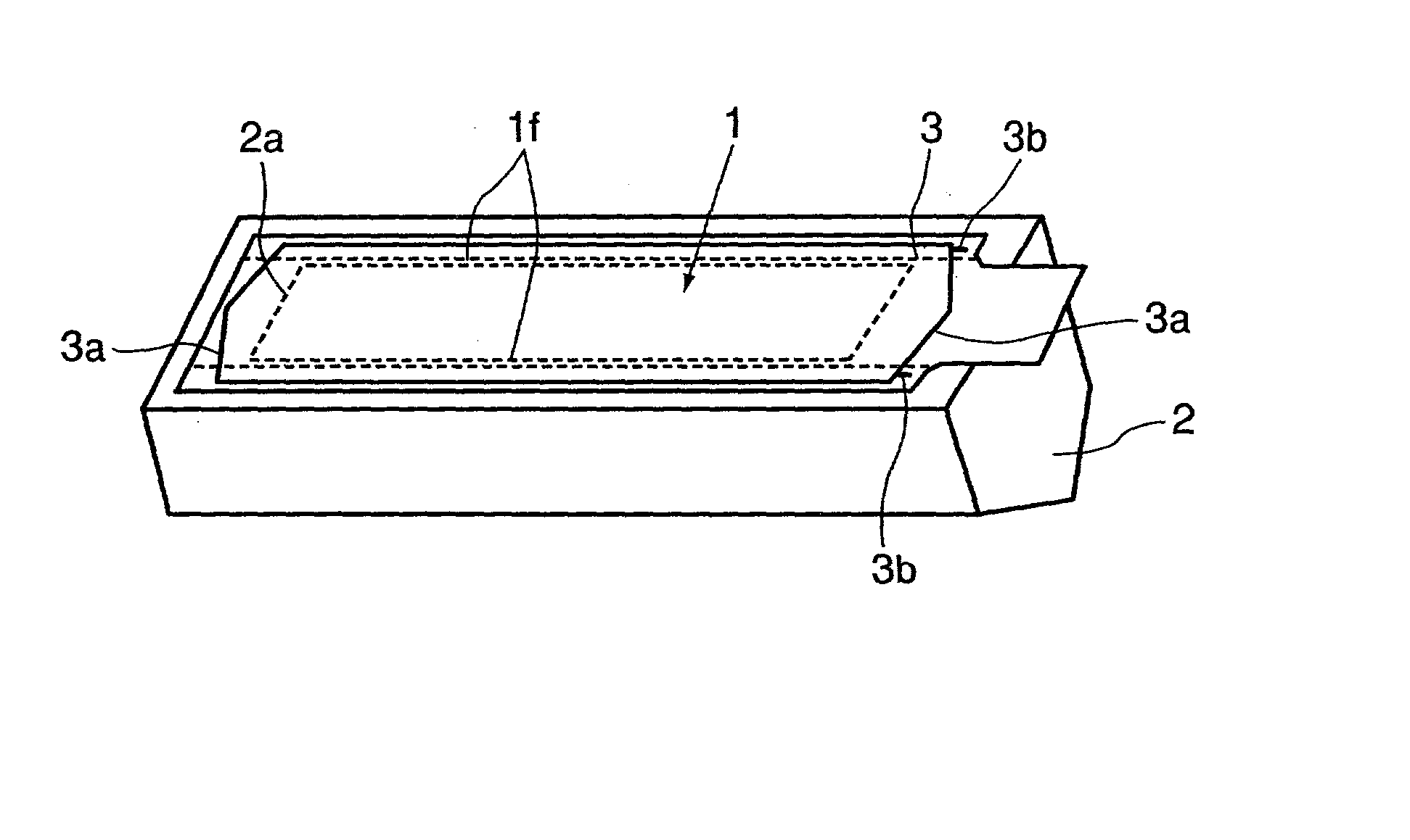
[0071] As shown in FIG. 13, at the longitudinal end portion 3a of the seal portion 3, there is provided a concave configuration 3a with respect to the unsealing direction C of the seal in the portion crossing with the tearing portion 1f of the toner seal member 1. More particularly, the configuration is arcuate, and the apex 3a is aligned with the tearing portion 1f. Here, the apex of arcuation is a contact point between the arcuation of the concave configuration is contacted with a line perpendicular the pulling direction of the toner seal member.

[0072] When the toner seal member 1 is removed, the edge portion 1j tends to ...

embodiment 3

[0077] (Embodiment 3)

[0078] In this embodiment, the toner seal member comprises a cover film 4 for sealing the toner discharging opening 2a and a tear tape 5 lined on the cover film 4 for tearing the cover film 4 with a width substantially equal to the toner discharging opening. This embodiment is similar to Embodiment 1 in other respects.

[0079] FIGS. 15, 16 show a toner seal member 1 of this embodiment. The cover film 4 sealing the toner discharging opening 2a comprises a layer of expansion bubble generation polypropylene layer (140 .mu.m (4a) and an EVA sealant layer (20 .mu.m (4b)).

[0080] The tear tape 5 comprises a polyester layer (16 .mu.m (5a)), an expansion nylon layer (25 .mu.m (5b)), a low density polyethylene layer (30 .mu.m (5c)) and an EVA sealant layer (40 .mu.m (5d)).

[0081] The cover film 4 and the tear tape 5 are welded to each other (between 4b and 5a) into a toner seal member 1, and is welded to the main body 2 on the toner supply container by heat seal, similarly t...

embodiment 1

[0082]

[0083] FIG. 17 is an enlarged view of a tearing start portion of the toner seal member.

[0084] Similarly to Embodiment 1, there is provided a rectilinear configuration 3c at the end portion of the extended seal portion 3b, and therefore, even the tearing start portion 4c portion is raised, and the force is produced in the peeling direction, the proper tearing can be assured. Thus, the cover film 4 can be assuredly torn. Furthermore, similarly to Embodiment 1, the rectilinear configuration 3c may be replaced with curve configuration such as an arcuation, and the similar advantageous effects can be provided.

[0085] As regards the assembling and manufacturing of the toner supply container, what is required is to weld the toner seal member on the main body 2 of the toner supply container. Therefore, the unsealing property stability can be accomplished with a very simple assembling.

[0086] Unsealing test has been carried out with the toner supply container of this embodiment, and it h...


PUM


Abstract

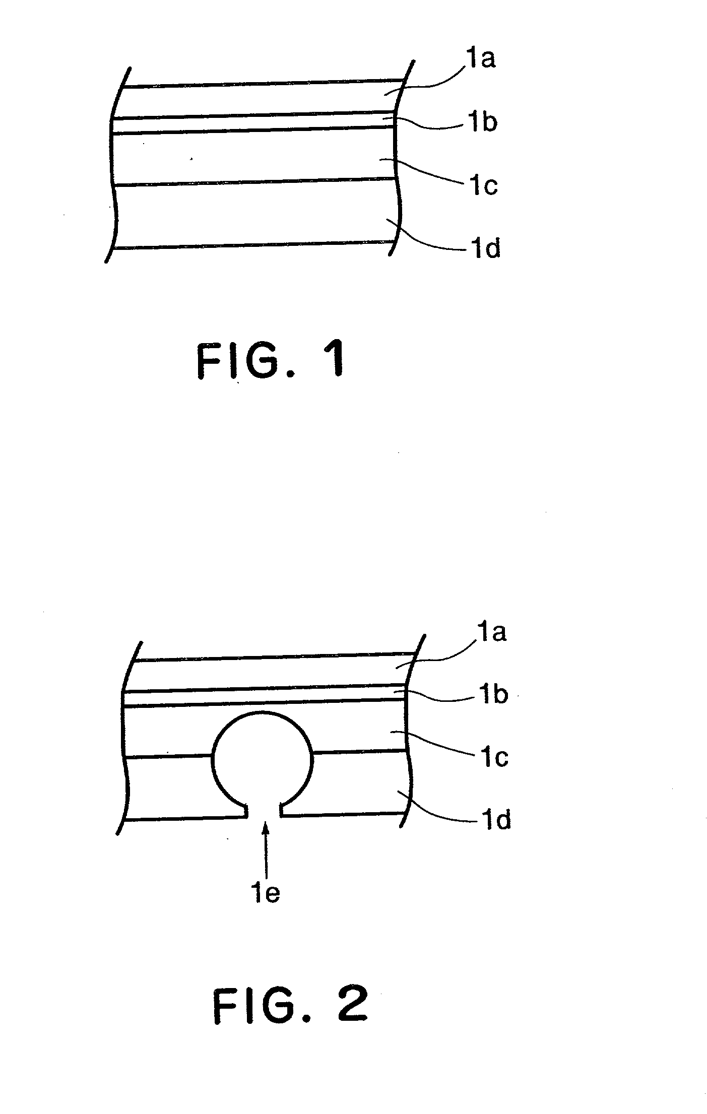
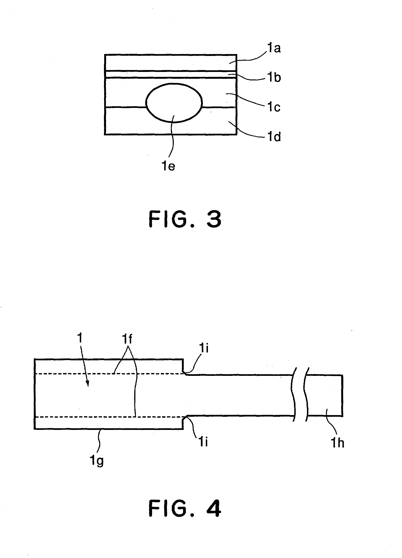
A toner supply container detachably mountable to an image forming apparatus, includes a main body, provided with an opening for permitting discharge of the toner, for accommodating the toner; a sealing member for unsealebly sealing the opening; wherein the opening is unsealed by tearing a part of the sealing member, wherein a pattern of welding with which the sealing member is welded on the main body of the container is inclined inwardly with respect to a tearing direction at a laterally outward end portion at a tearing starting side end portion.

Description

FIELD OF THE INVENTION AND RELATED ART[0001] The present invention relates to a toner supply container for supplying toner into an image forming apparatus of an electrostatic recording type, an electrophotographic type or the like, such as a copying machine, a printer, a facsimile machine or the like, and to a process cartridge detachably mountable to the image forming apparatus.[0002] In an image forming apparatus such as an electrostatic copying machine, printer and the like, powdery toner is used, and is supplied with toner from a toner supply container. The toner supply container generally comprises a cylindrical, rectangular parallelopiped or the like shape main body made of synthetic resin material, and a toner seal member for sealing an opening of the main body provided to permit supply of the powdery toner into a developing device.[0003] More particularly, in an image forming apparatus using an electrophotographic image forming process, a cartridge integrally containing an e...

Claims


Application Information

Patent Timeline
IPC IPC(8): B65D83/06G03G15/08
CPCG03G2215/069G03G15/0884
Inventor NAGASHIMA, TOSHIAKIOMATA, KAZUHIKO
Owner CANON KK
Learn More