
Aperture stop changing device for camera

a technology of aperture stop and camera, which is applied in the direction of camera diaphragm, camera body details, instruments, etc., can solve the problems of reducing product size and increasing the number of required parts

Inactive Publication Date: 2002-07-11
FUJIFILM HLDG CORP +1
View PDF2 Cites 4 Cited by
  • Summary
  • Abstract
  • Description
  • Claims
  • Application Information

AI Technical Summary

Benefits of technology

[0009] Another object of the present invention is to provide an aperture stop changing device for a camera in which an aperture changing plate can be positioned to move on a suitable plane, and can be prevented from interference with a lens surface.
[0028] Furthermore, a ring-shaped flare stopper is disposed close to the first or second lens element, for blocking light traveling away from the light path of the object light, to prevent flare.

Problems solved by technology

If the aperture changing plate is inserted between the lens elements, it is likely that an end or tip of the aperture changing plate contacts and interferes with a lens surface to scratch or damage the same.
However, this raises the number of the required parts, and is inconsistent to reducing the product size.

Method used


Image

  • Aperture stop changing device for camera
  • Aperture stop changing device for camera
  • Aperture stop changing device for camera

Examples


Embodiment Construction

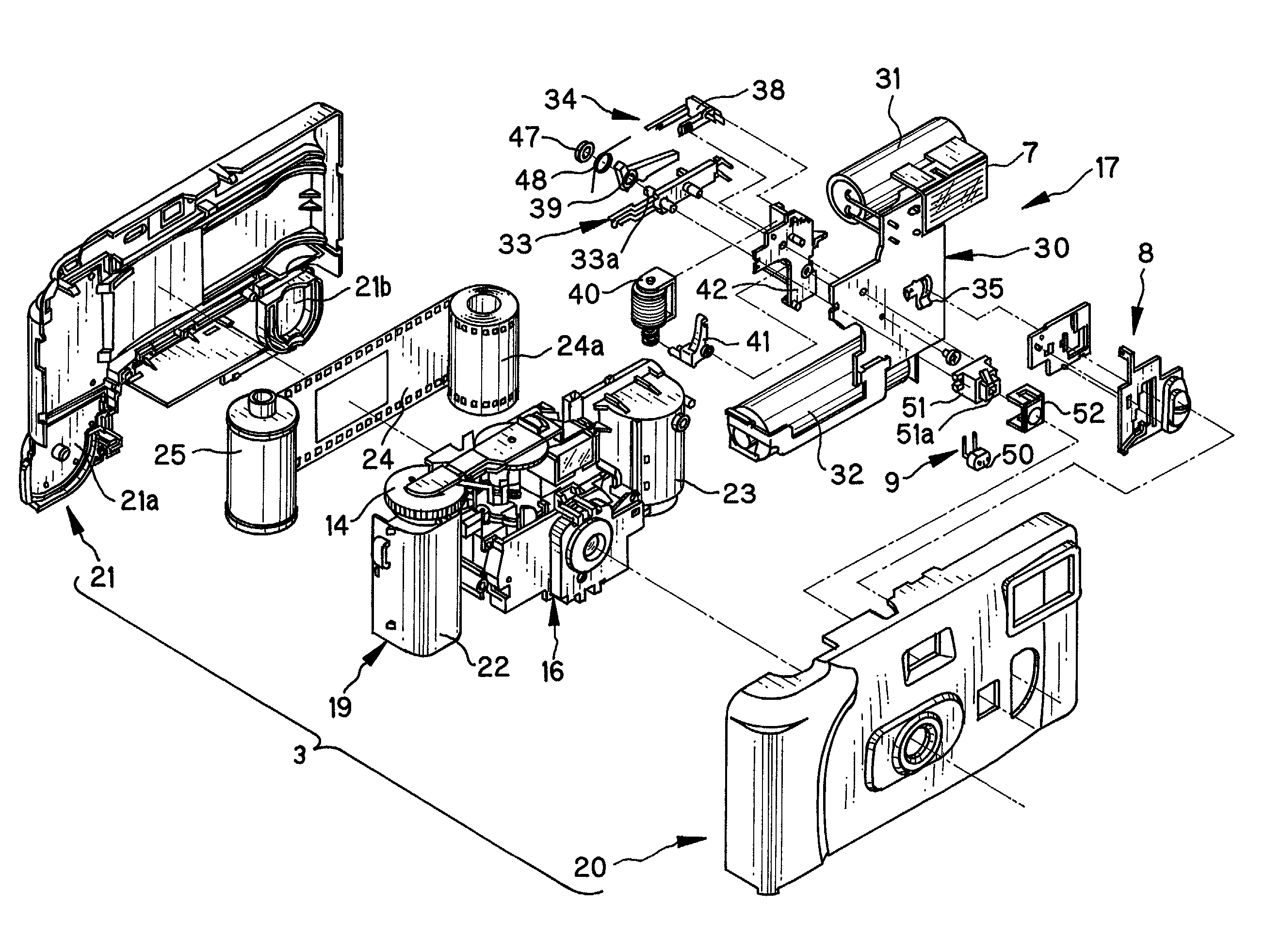
[0052] In FIG. 1, a camera or lens-fitted photo film unit 2 is illustrated. The lens-fitted photo film unit 2 includes a housing 3 and a sticker belt 4. The housing 3 accommodates a construction for taking an exposure. The sticker belt 4 covers a portion of the outer surface of the housing 3. A front of the housing 3 has a taking lens 5, a viewfinder objective window 6, a flash emitter 7, a flash charger button 8 and a photometric unit 9. An upper side of the housing 3 has a shutter release button 11, a frame counter window 12 and a light guide 13. The frame counter window 12 indicates the number of remaining frames available for exposures. The light guide 13 illuminates to indicate a state of completion of charging the flash. The rear of the housing 3 has a winder wheel 14, an eyepiece viewfinder window and the like.

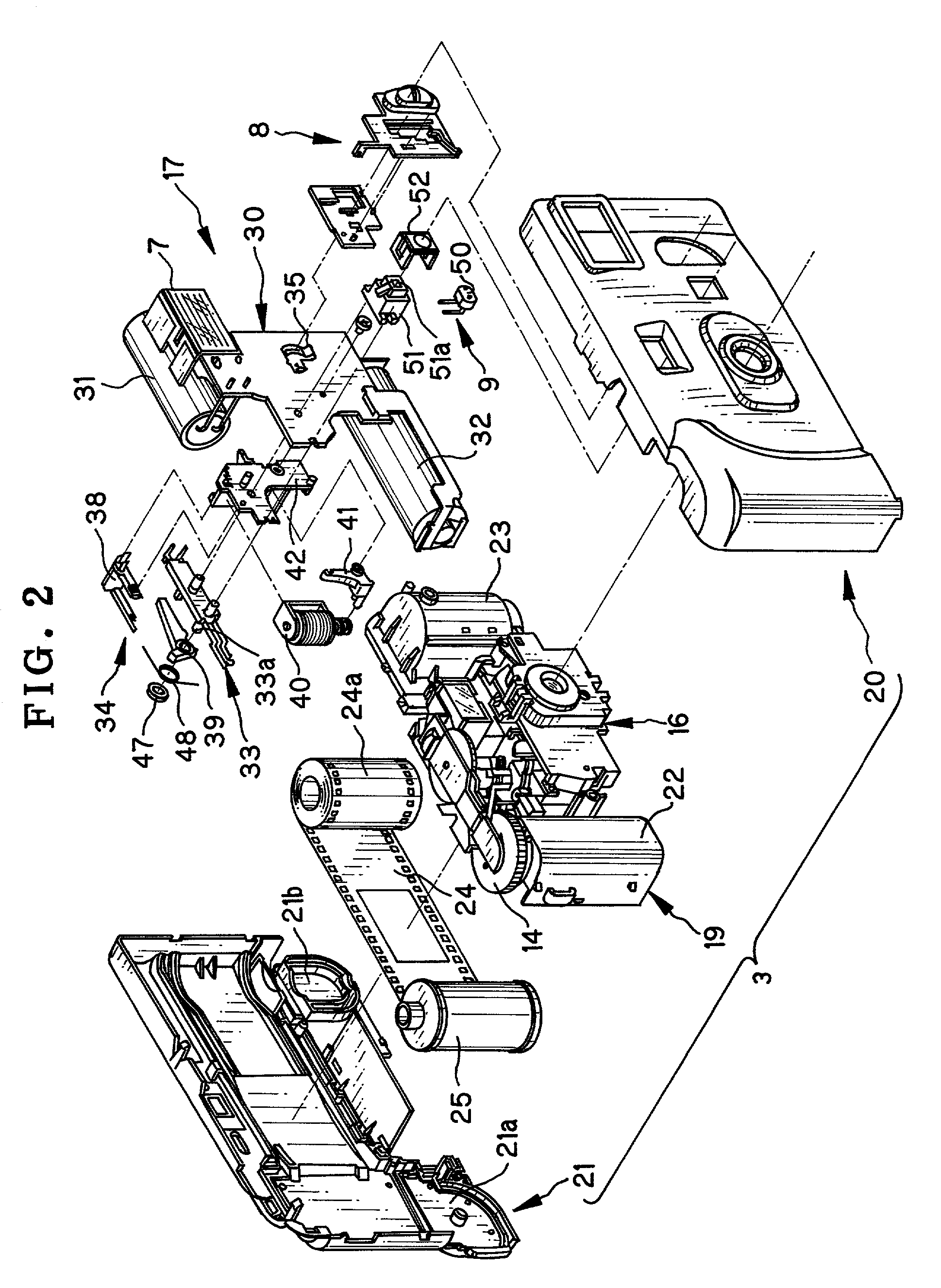
[0053] In FIG. 2, the housing 3 includes a main body 19, a front cover 20 and a rear cover 21. The main body 19 includes an exposure unit 16 and a flash unit 17. The fr...


PUM


Abstract

A camera includes a preset open aperture for introducing object light to photo film. A taking lens is disposed in a light path of the object light, and has two lens elements. In the camera, an aperture stop changing device is provided. An aperture changing plate includes a stop-down opening having a small diameter, is disposed close to the taking lens, is movable between a small diameter position and a large diameter position. The stop-down opening, when the aperture changing plate is in the small diameter position, is set in the light path for stopping down the preset open aperture, and when the aperture changing plate is in the large diameter position, is set away from the light path. A spacer is secured to a partial section of a peripheral portion of the taking lens, for defining a passage gap or cutout at a remaining partial section of the peripheral portion of the taking lens. The passage cutout allows passage of the aperture changing plate moving between the small and large diameter positions.

Description

[0001] 1. Field of the Invention[0002] The present invention relates to an aperture stop changing device for a camera. More particularly, the present invention relates to an aperture stop changing device for a camera having a simple structure, and also in which performance of a taking lens can be free from being influenced by the relevant elements for the aperture stop changing.[0003] 2. Description Related to the Prior Art[0004] A lens-fitted photo film unit is a single use camera pre-loaded with photo film. Various mechanisms and elements in the lens-fitted photo film unit are simplified for the purpose of lowering the manufacturing cost. The lens-fitted photo film unit includes a shutter unit which a single shutter blade is biased in a closed position, and is knocked instantaneously toward an open position so as to take an exposure by opening and closing a shutter opening. In addition to the shutter unit, the lens-fitted photo film unit is provided with an aperture stop changing ...

Claims


Application Information

Patent Timeline
IPC IPC(8): G03B9/02
CPCG03B9/02
Inventor MIKAMI, YUJI
Owner FUJIFILM HLDG CORP
Learn More