
Radio communication apparatus

a radio communication and apparatus technology, applied in the direction of radio transmission, electrical equipment, substation equipment, etc., can solve the problems of reducing the reception sensitivity of the radio communication apparatus, the gps receiver in the cellular phone cannot receive gps signals, and the usefulness of the gps function of the cellular phone when used inside the vehicl

Inactive Publication Date: 2002-06-27
KK TOSHIBA
View PDF7 Cites 53 Cited by
  • Summary
  • Abstract
  • Description
  • Claims
  • Application Information

AI Technical Summary

Benefits of technology

[0015] Such a configuration becomes free from fear of causing interference of a radio frequency signal received by a radio communication relay unit with that received by the first or second antenna, that is, interference between signals in the same radio frequency. This can provide reception quality being kept high.

Problems solved by technology

This shielding causes significant degradation in reception sensitivity of the radio communication apparatus when operated inside a vehicle.
However, a GPS receiver in the cellular phone cannot receive GPS signals due to the electromagnetic shielding of the vehicle.
In this example, the usefulness of the GPS function of the cellular phone diminishes when used inside a vehicle.
This requirement of separate antenna connections for a multipurpose radio communication device has been a significant barrier to downsizing.

Method used


Image

  • Radio communication apparatus
  • Radio communication apparatus
  • Radio communication apparatus

Examples


first embodiment

[0022] First Embodiment

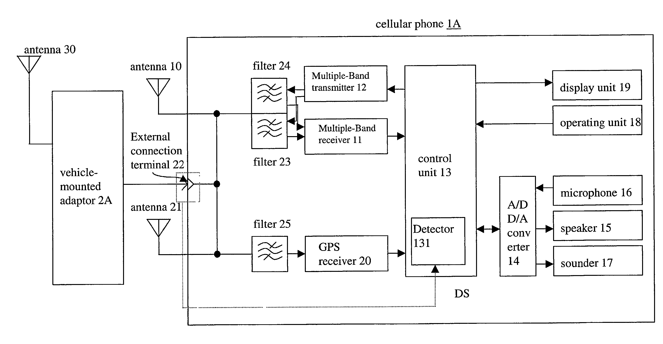
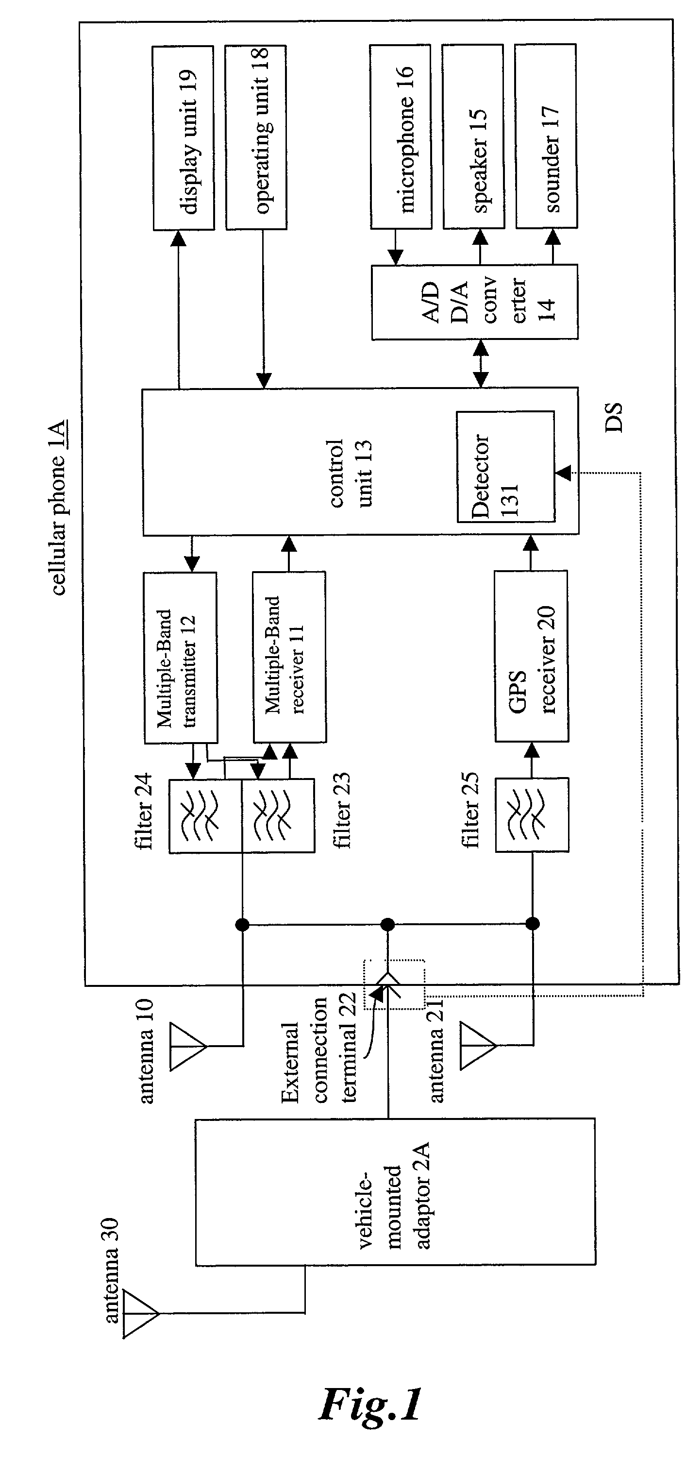
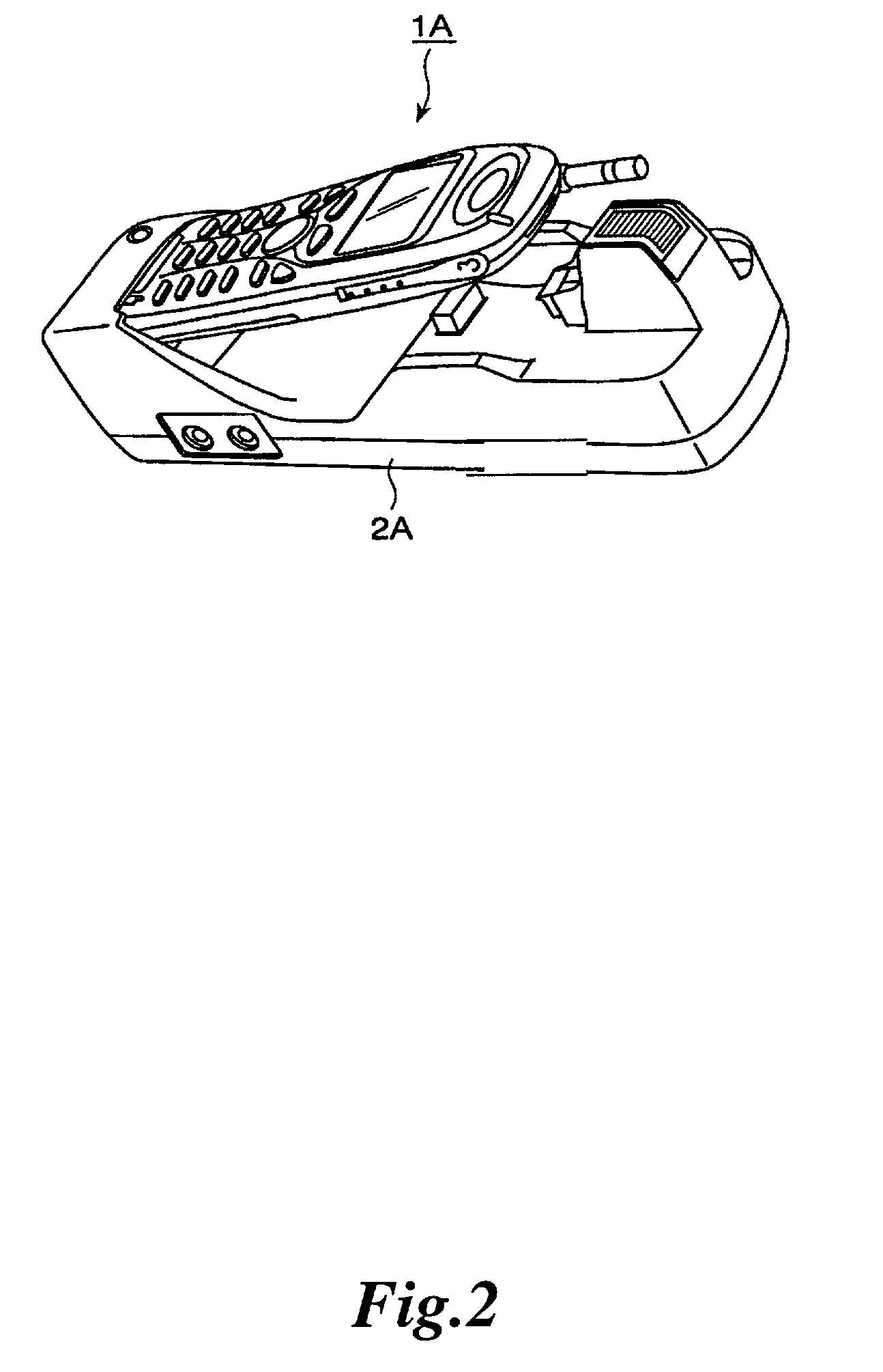
[0023] FIG. 1 is a block diagram showing a functional configuration of a multiple-band, multiple-band-capable, and / or vehicle-mounted-compatible cellular phone with a vehicle-mounted adapter. FIG. 2 is a perspective view showing the cellular phone connecting to the vehicle-mounted adapter.

[0024] The cellular phone 1A is a kind of a radio communication apparatus and the vehicle-mounted adapter is a kind of a radio communication relay unit. Other alternatives for the radio communication apparatus and radio communication relay unit are known.

[0025] In FIG. 1, a cellular phone 1A has a multiple-band receiver 11 and a multiple-band transmitter 12. The multiple-band receiver 11 can receive, for example, 900 MHz and 1.8 GHz radio frequency signals, among others. It is appreciated that the multi-band transmitter 12 and receiver 11 may include single band, dual band, tri-band and additional band capability. The multiple-band transmitter 12 can transmit 900 MHz and 1.8 ...

second embodiment

[0060] Second embodiment

[0061] FIG. 3 is a block diagram showing a functional configuration of a vehicle-mounted-compatible cellular phone with a vehicle-mounted adapter as a second embodiment of a radio communication apparatus according to the present invention. In FIG. 2, the same constituents as those in FIG. 1 are denoted by the same reference numerals with detailed explanations for those constituents omitted.

[0062] A switch 26 is provided between the antenna 10 of a cellular phone 1B and the band-pass filters 23 and 24, a switch 27 is provided between the antenna 21 of the cellular phone 1B and the GPS reception band-pass filter 25. The switch 26 and 27 are operated by a control signal SWa from a control unit 13.

[0063] The control unit 13 has a mode decision function, and a switching control function for switching 26 and 27.

[0064] The mode decision function is for making a decision on the basis of the detection signal DS the adapter detector 131 detects as to the cellular phone...


PUM


Abstract

In a radio communication apparatus, band-pass filters are provided in correspondence with a multiple-band receiver, a multiple-band transmitter and a GPS receiver, respectively. As radio frequency signals received by an external antenna on a vehicle-mounted adapter is inputted to the radio communication apparatus through the external connection terminal 22, signals in necessary frequency bands are passed by the band-pass filters so as to be inputted to the multiple-band receiver and the GPS receiver, respectively. This makes it possible for the connection terminal to be shared in radio communication by a cellular phone and in GPS reception with reception quality kept high both in the radio communication and the GPS reception to allow the number of external connection terminals to be reduced for providing further downsized and lightweight radio communication apparatus.

Description

RELATED APPLICATION INFORMATION[0001] This disclosure is related to and claims priority to Japanese Patent application P2000-367358, whose contents are expressly incorporated herein by reference.[0002] 1. Field of the Invention[0003] The present invention relates to a radio communication apparatus, and more particularly, to a radio communication apparatus using an antenna with multiple receivers or transceivers.[0004] 2. Description of the Related Art[0005] With recently developed communication technologies and increasing communication needs, radio communication apparatuses such as cellular phones or PDAs (Personal Digital Assistants) with radio communication functions have become popular. The radio communication apparatuses, which are generally designed for operation outdoors or indoors beside a window, are affected by electromagnetic shielding. This shielding causes significant degradation in reception sensitivity of the radio communication apparatus when operated inside a vehicle...

Claims


Application Information

Patent Timeline
IPC IPC(8): H04M1/00H04B1/38H04B1/40H04B7/26H04M1/725H04W16/28H04W88/02H04W88/06
CPCH04B1/0003H04B1/005H04B1/406H04B1/3805H04B1/006
Inventor YOSHIDA, HIRONORIISHIKURA, AKIRAMIZUMOTO, TORU
Owner KK TOSHIBA
Learn More