
Sandwich acoustic panel

Inactive Publication Date: 2002-06-13
AIRBUS OPERATIONS SAS
View PDF0 Cites 26 Cited by
  • Summary
  • Abstract
  • Description
  • Claims
  • Application Information

AI Technical Summary

Benefits of technology

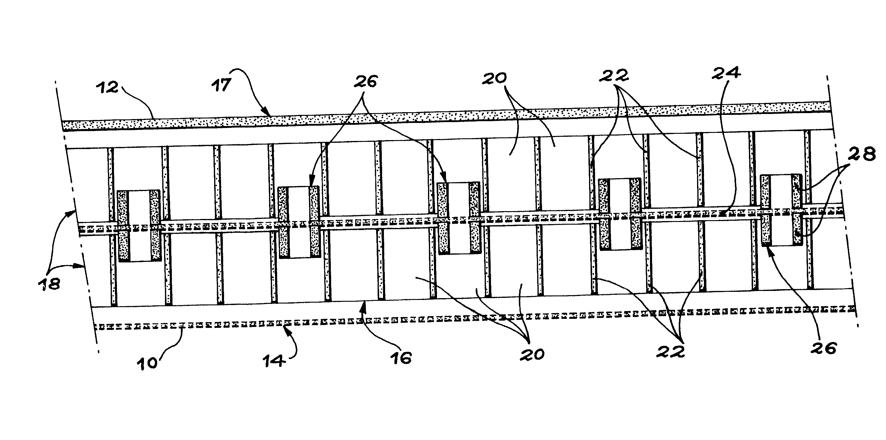
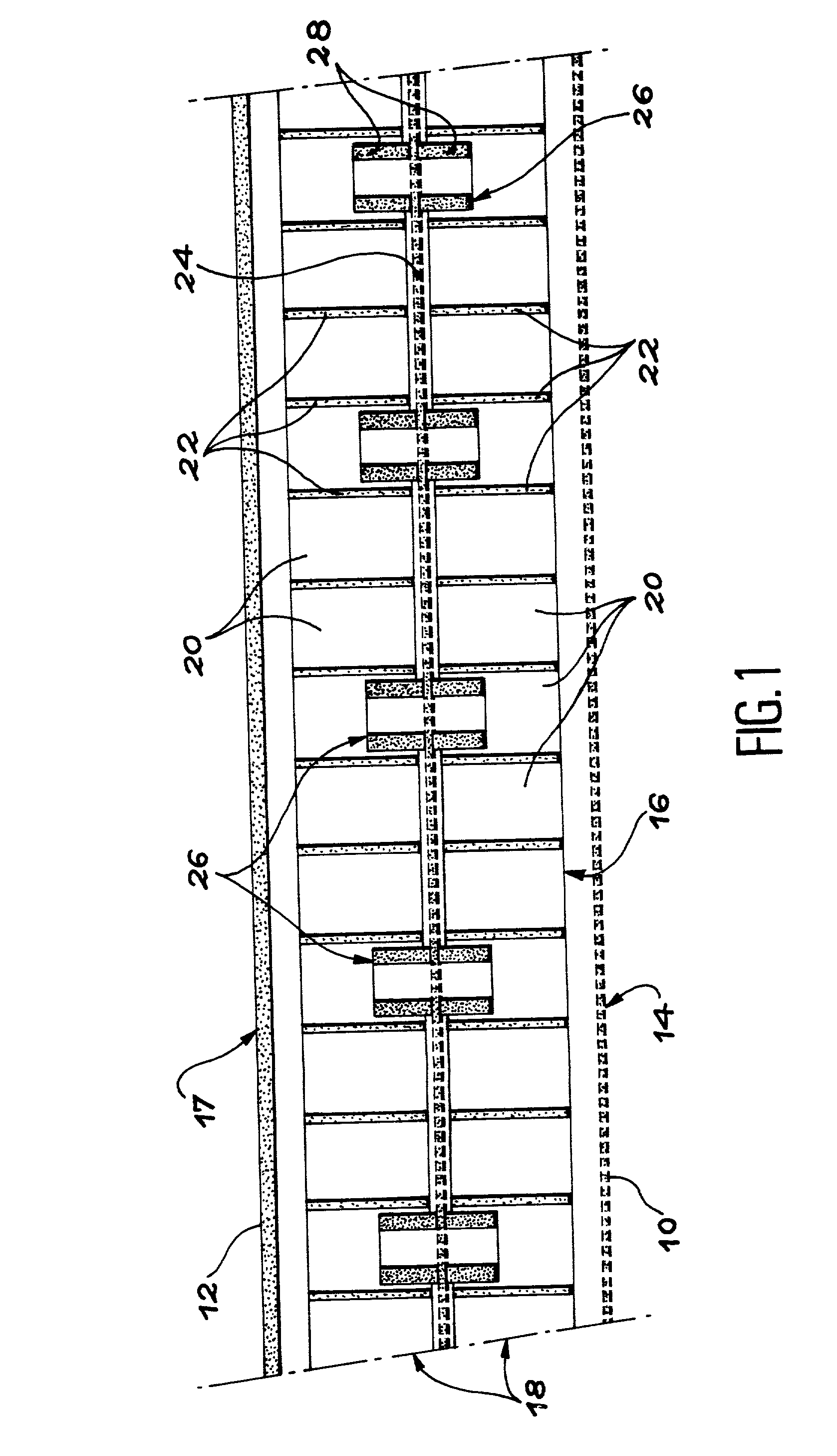
[0026] The presence of guides on each face of the porous separator makes it possible for partitions, and consequently cells of the compartmentalized structure, to be made continuous between the inner surface of the resistive layer and the reflector. Therefore local misalignment problems of cells that necessarily occur on panels with several degrees of freedom according to prior art, composed of several superposed compartmentalized structures, are eliminated. Consequently, risks of non-homogeneity no longer exist.

Problems solved by technology

Failure to respect this requirement depends on the nature of the elements making up the panel, their relative layout and adhesives used for their assembly.
If this requirement is not satisfied, then there is a transverse propagation of sound waves called "lateral energy leak" inside the panel, which opposes "quarter wave" type operation of the compartmentalized structure.
On the other hand, it has the disadvantage that it is acoustically very non-linear and that the strength is very dependent on the tangential flow velocity at the surface.
Furthermore, since the frequency damped by each cell depends on its depth, and since the depth of all cells in the panel is the same, the frequency range damped by this type of panel is restricted.
Furthermore, when the resistive layer is made of a composite material, the structure has low resistance to erosion.
However, the production of a sandwich panel with a linear single degree of freedom is more complicated than the construction of a panel with a non-linear single degree of freedom, since the resistive layer comprises two components.
If the components or assembly processes are not controlled, the structure may comprise areas of acoustic non-homogeneity, or risks of delamination of the resistive layer.
Furthermore, risks of corrosion in the resistive layer impose an additional constraint on the choice of the material used.
Furthermore, the process for assembly of this type of panel is long and expensive.
However, acoustic panels with two degrees of freedom have the disadvantage that areas of acoustic non-homogeneity occur due to poor alignment of the cells in the two compartmentalized cores, that inevitably occurs when the panel is being formed.
Finally, the process for assembly of a panel of this type is long and expensive, since the various elements of the structure have to assembled one by one.

Method used


Image

  • Sandwich acoustic panel
  • Sandwich acoustic panel
  • Sandwich acoustic panel

Examples


Embodiment Construction

[0035] As shown diagrammatically in FIG. 1, a sandwich acoustic panel conform with the invention is composed of a stack of several constituents fixed to each other. To facilitate understanding, these constituents are shown slightly separated from each other. In practice, they are in close contact over the entire surface of the panel.

[0036] The acoustic panel according to the invention may be plane, as shown as an example. However, it may also be in any other shape, and particularly a curved shape as is the case in which it is integrated in the pod or engine casing of a turbojet.

[0037] The structure of the panel will now be described starting from the outside face 10 of the panel called the "front face", and working in order towards its inside face 12, called the "back face". In the figure, the front face 10 and the back face 12 are facing the bottom and top respectively.

[0038] Thus, starting from the front face 10, the acoustic panel according to the invention comprises a resistive ...


PUM


Abstract

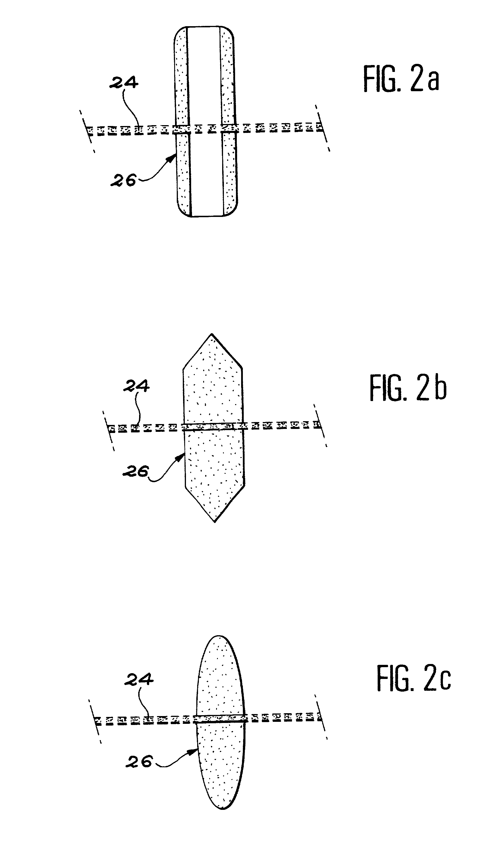
An acoustic panel with several degrees of freedom comprises a resistive layer (14), a compartmentalized structure (16) formed from at least two superposed compartmentalized layers (18) and a back reflector (17), starting from an outside face facing an incident acoustic wave. A porous separator (24) is placed between each pair of adjacent compartmentalized layers. On each of its faces, this separator is fitted with tubular guides (26) that penetrate into at least some of the cells (20) of the compartmentalized layers. This thus aligns the cells over the entire thickness of the compartmentalized structure (24), regardless of the shape of the panel.

Description

TECHNICAL DOMAIN[0001] The invention relates to a sandwich acoustic panel, in other words a noise reducing sandwich panel designed to attenuate an incident sound wave facing an outside face of the panel.[0002] In particular, an acoustic panel according to the invention may be used in the walls of pods or turbojet casings, or in ducts to be soundproofed, etc.STATE OF THE ART[0003] Existing acoustic panels usually comprise one or several quarter wave resonators superposed on a total reflector. Each resonator itself is composed of a resistive layer that is more or less permeable to air, and a compartmentalized structure, usually of the honeycomb type. The resistive layer covers the face of the compartmentalized structure facing outside, in other words towards the incident sound wave. On the other hand, the total reflector covers the face of the resonator opposite this incident wave. By convention, the "front face" is the side of the panel on which the resistive layer is placed, and the...

Claims


Application Information

Patent Timeline
IPC IPC(8): G10K11/172
CPCG10K11/172
Inventor PORTE, ALAINLALANE, JACQUES
Owner AIRBUS OPERATIONS SAS
Learn More