
System for toll payment and transportation management

Inactive Publication Date: 2002-06-06
NEC CORP
View PDF2 Cites 56 Cited by
  • Summary
  • Abstract
  • Description
  • Claims
  • Application Information

AI Technical Summary

Benefits of technology

[0019] According to the present invention, the toll gate does not need to identify a kind of car, because the kind of car is identified by the car ID transmitted to ISP. Further, any special transmission channel is not required, because conventional portable telephone is used. Further, any special apparatus for identifying car location, because the location information offered by the portable telephone, or GPS is used. Further, various internet electronic payment system can be used, because the car is connected with ISP. Further, the toll gate does not need to identify the driving distance and section, because the location information from the telephone company can be utilized. Further, unfair actions are prevented and safety of highway is supervised by the monitoring video camera. Thus, facilities cost is reduced greatly.
[0020] The above-mentioned cost reduction causes further cost reduction in toll collection and all the other communication costs and further reduction of the traffic jam at the toll gate.

Problems solved by technology

Toll payments at a gate cause usually a traffic jam.
The conventional toll payment has a disadvantage that special lanes for the electronic payment must be provided together with conventional lanes for cash and prepaid cards.
Therefore, the traffic jam at the gate may become heavier, in spite of the fact that it costs much to construct these lanes.
GPS may be needless, when a barrier is provided at the toll gate to shield electromagnetic waves from conventional radio base stations and when a radio base station exclusively used for each toll gate is provided.

Method used


Image

  • System for toll payment and transportation management
  • System for toll payment and transportation management
  • System for toll payment and transportation management

Examples


Embodiment Construction

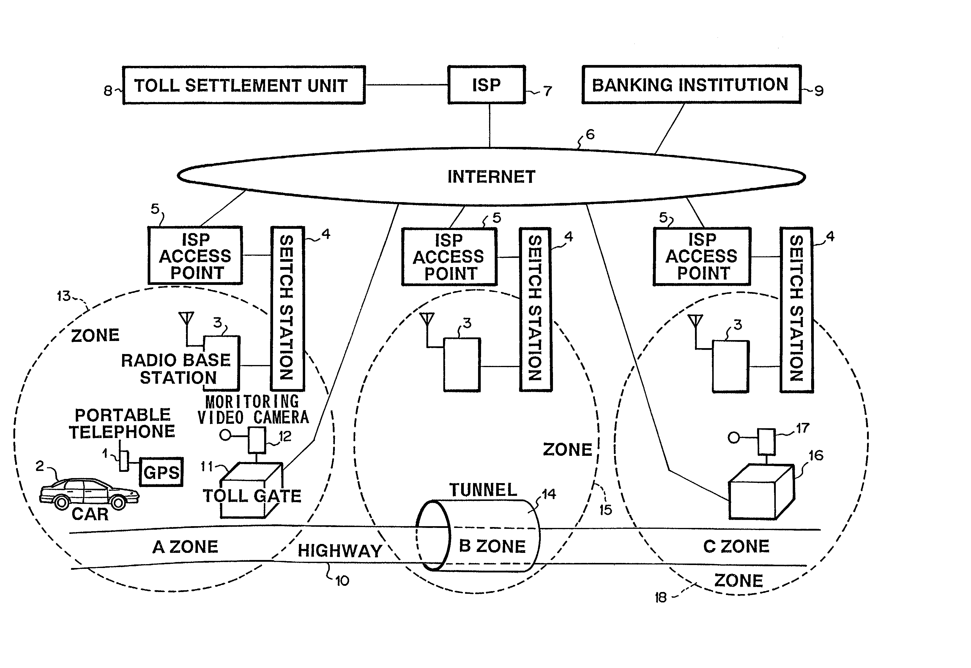
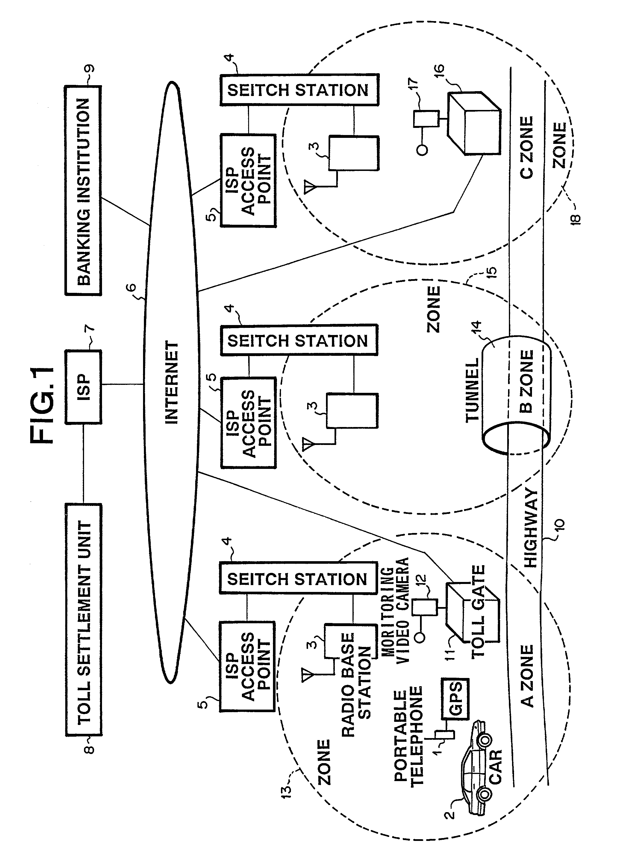
[0029] FIG. 1 is a block diagram of an embodiment of the present invention.

[0030] Portable telephone 1 is an information terminal carried by a driver of car 2. Portable terminal 1 is connected with radio base station 3 which is connected, through switch station 4 and ISP access point 5, with internet 6. Further, internet 6 is connected through ISP 7 with toll payment unit 8. Further, a sever or toll payment unit 8 is connected through internet 6 with banking institution 9.

[0031] Radio base stations 3 are provided at prescribed locations along a highway. Concretely, entrance toll gate 11 is provided with monitoring video camera 12 for photographing car 2 passing through entrance toll gate 11. Radio base station 3 at entrance toll gate 11 communicates with portable telephone 1 in radio zone A 13. Other radio base station 3 which controls radio zone B 15 communicates with portable telephone 1, although it can not communicate with portable telephone 1, when portable telephone 1 is in tu...


PUM


Abstract

An object of the present invention is to pay a toll without stopping a car and without providing a special lane for electronic payment, thereby reducing a traffic jam. The toll payment system comprises a portable telephone on a car, a base station connected with the portable telephone, a server connected with the base station. The server comprises a first memory for storing a location of the base station, a second memory for storing a unit price for each section along the highway and data identifying a contractor or contracted car, a driving route identification unit for identifying a driving route on the basis of the location stored in the first memory and a base station connected under a certain manner, a toll calculation, and a charging unit.

Description

[0001] 1. Technical Field of the Invention[0002] The present invention relates to an electronic toll payment system for a highway toll and a transportation management system.[0003] 2. Description of the Prior Art[0004] Toll payments at a gate cause usually a traffic jam. Therefore, prepaid cards and coupon tickets are used for shortening time spent for the payment. Further, wireless communication is used for an electronic payment without stopping a car, as disclosed in JP 6-59947 U (1994).[0005] Further, a portable telephone is used in JP 11-110593 A (1999) for avoiding special apparatus.[0006] However, these electronic payments as mentioned above require an apparatus for identifying a car which passes the toll gate.[0007] The identifying apparatus at the gate is large-scaled, because it has to determine, for preventing unfair actions, a toll which depends upon a car size, driving distance and driving section on the highway, on the basis of distinctive features of the car or a speci...

Claims


Application Information

Patent Timeline
IPC IPC(8): G07B15/00G08G1/00G08G1/017G08G1/065G08G1/09
CPCG07B15/063G08G1/065G08G1/017
Inventor IKEDA, SABUROU
Owner NEC CORP
Learn More