
Closed ink delivery system with print head ink pressure control and method of same

Inactive Publication Date: 2002-04-25
HEWLETT PACKARD IND PRINTING LTD
View PDF0 Cites 126 Cited by
  • Summary
  • Abstract
  • Description
  • Claims
  • Application Information

AI Technical Summary

Problems solved by technology

The ink is periodically replenished from the stationary tank to the movable tank, however the amount of ink stored in the movable tank is very small and it has a complicated structure that is not suitable to By applications.
Other printing systems dearate ink by applying vacuum close to the print heads, thus complicating the structure of the print head.

Method used


Image

  • Closed ink delivery system with print head ink pressure control and method of same
  • Closed ink delivery system with print head ink pressure control and method of same
  • Closed ink delivery system with print head ink pressure control and method of same

Examples


Embodiment Construction

[0015] In the following detailed description, numerous specific details are set forth in order to provide a thorough understanding of the invention However, it will be understood by those skilled in the art that the present invention may be practiced without these specific details. In other instances, well-known methods, procedures, and components have not been described in detail so as not to obscure the present invention.

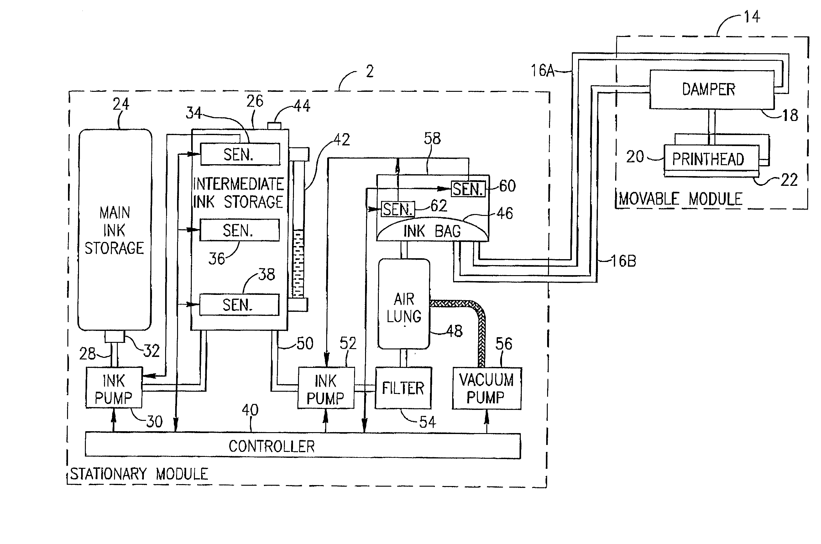
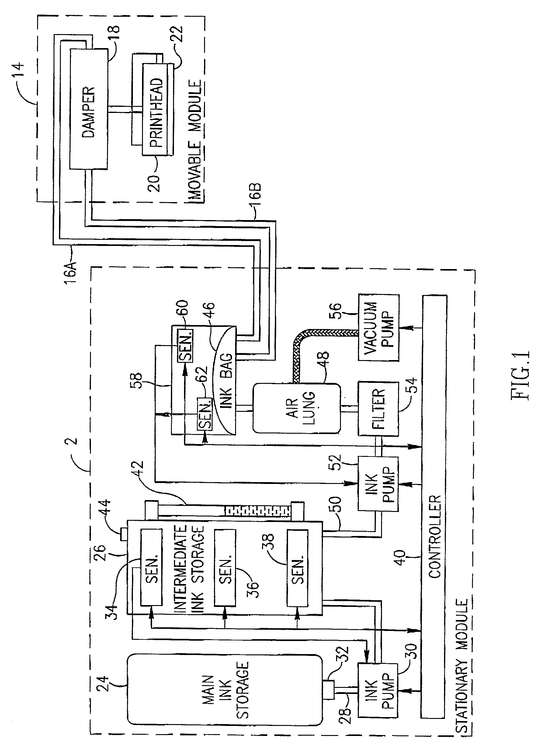
[0016] Reference is now made to FIG. 1 which is a schematic block diagram of an inking system, generally designated 10 according to some embodiments of the present invention.

[0017] Inking system 10 may comprise a stationary module 12 and a movable module 14 coupled to stationary module 12 via flexible pipes 16. Movable module 14 may comprise a damper 18 coupled via pipes to one or more print heads 20. A valve (not shown) capable of switching on and off the ink flow to a respective print head 20 may be coupled to each pipe Each print head may comprise a plurality o...


PUM


Abstract

In some embodiments of the present invention, an ink supply system is provided. The system is configured to expose ink to the ambient atmosphere only at the nozzles of one or more print heads coupled to the system.

Description

[0001] The present application claims priority from both US provisional application Ser. No. 60 / 242,141, filed Oct. 23, 2000 and US provisional application Ser. No. 60 / 288,817, filed May 7, 2001.BACKGROUND OF THE MENTION[0002] Industrial inkjet printers are typically large format machines capable of printing on various subsumes at high printing speeds. L these machines, the print head may comprise a linear or a two-dimensional array of nozzles. Continuous printing on large formats at high printing speeds and with a large number of nozzles requires a continuous supply of relatively large amounts of ink. In order to ensure the quality of printings it is desirable to use dearated ink, to reduce fluctuations in the ink pressure and to maintain the ink pressure at the print-head lower than the ambient atmospheric level.[0003] Some printing systems use an ink supply system that comprises a large stationary ink tank, and a small movable tank that moves along with the print head. The ink is...

Claims


Application Information

Patent Timeline
IPC IPC(8): B41J2/175B41J2/19B41J11/42B41J13/00B41J29/08
CPCB41J2/175B41J2/19B41J29/08B41J13/0072B41J11/42
Inventor KARLINSKI, HAGGAIAMBAR, RAFAELGOLDMAN, YOSSIMARKMAN, ALEXFISHER, GILVORONSKI, ELIFEINER, DAVID
Owner HEWLETT PACKARD IND PRINTING LTD
Learn More