
Piston for a four-stroke internal combustion engine

a four-stroke internal combustion engine and piston technology, applied in the direction of trunk pistons, cylinders, plungers, etc., can solve the problem of not being able to achieve oil drain passages, and achieve the effect of reducing oil consumption

Inactive Publication Date: 2002-02-28
AVL LIST GMBH
View PDF0 Cites 17 Cited by
  • Summary
  • Abstract
  • Description
  • Claims
  • Application Information

AI Technical Summary

Benefits of technology

[0003] In U.S. Pat. No. 5,133,563 a piston is described whose piston head is provided with only two piston rings. The lower, second groove is designed to carry an L-ring whose shorter leg points towards the crankcase. This is intended to minimize oil consumption.
[0004] It is an object of this invention to further reduce oil consumption in a piston of the above mentioned type.
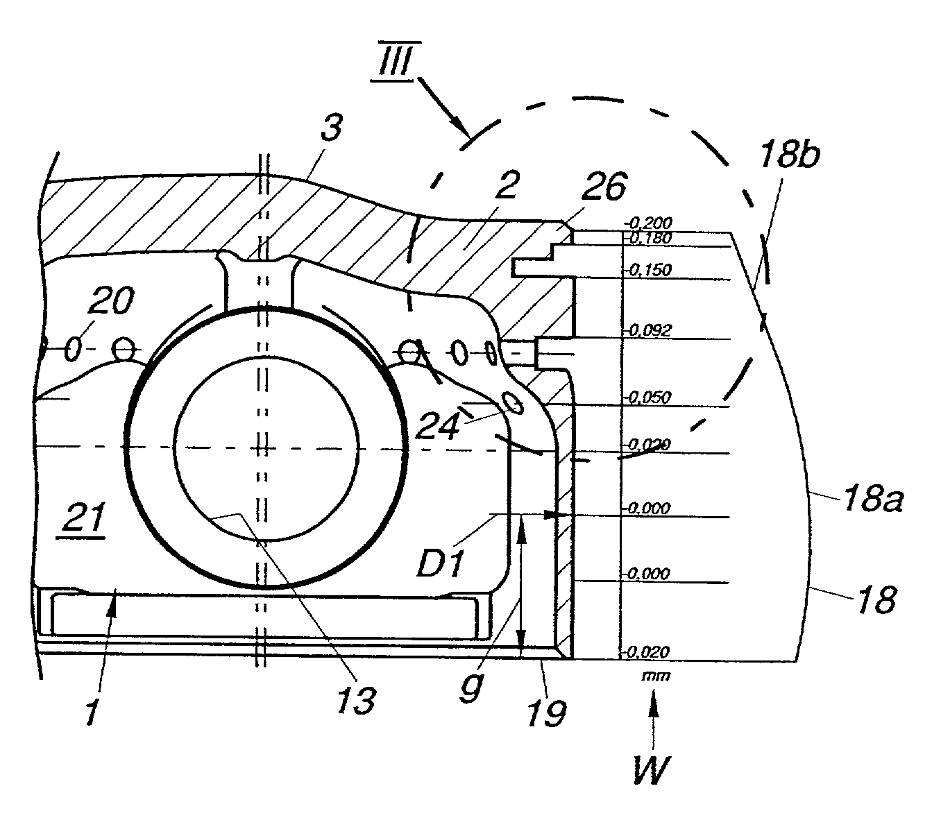
[0005] According to the invention this object is achieved by configuring the piston ring land between the two grooves as second guide face for guiding the piston. In addition to the piston rings this second guide face which is thus generated between the two grooves, will provide an additional seal, which will significantly reduce oil consumption compared to known piston types with two piston rings. In addition, the well-known phenomenon of piston slap will be reduced or even eliminated, and piston noise will be kept low.
[0006] In order to further improve sealing, it is proposed that the first groove be given an essentially L-shaped cross-section to hold the compression ring designed as L-ring, the longer leg of the "L" of the first groove extending in the wall of the piston head in radial direction, and the shorter leg of the "L" in axial direction, pointing towards the piston top, the long, radial leg of the first groove preferably constituting a radial guide for the L-ring. The short, axial leg of the first groove has larger dimensions in radial and axial direction than the corresponding compression part of the L-ring to be held in it. As a consequence, a gap will form between piston head and piston ring, into which compressed gas may penetrate, thus forcing the L-ring outwards. As a result, sealing will increase with an increase in pressure. The piston ring thus will require only little preloading and friction losses will be kept low.
[0007] Excellent oil scraping properties with little friction may be obtained by providing the second groove with an essentially rectangular cross-section for holding the oil scraper ring, preferably with several first oil drain passages leading into the piston interior from the bottom of the second groove. The first oil drain passages departing from the bottom of the second groove will allow the excess oil scraped off from the cylinder wall to flow towards the interior of the piston. To improve the transport of oil from the oil scraper ring to the piston interior it is proposed in further development of the invention that adjacent to the second groove on the side facing the piston skirt a bevelled surface inclined relative to the second groove be formed in the piston wall and that a plurality of second oil drain passages depart from the bevelled surface to lead into the piston interior.
[0011] To reduce friction losses it will be of advantage if the piston pin bearing is configured as a needle bearing.

Problems solved by technology

For structural reasons no oil drain passages are possible in the area of the piston pin bore.

Method used


Image

  • Piston for a four-stroke internal combustion engine
  • Piston for a four-stroke internal combustion engine
  • Piston for a four-stroke internal combustion engine

Examples


Embodiment Construction

with reference to the accompanying drawings, in which

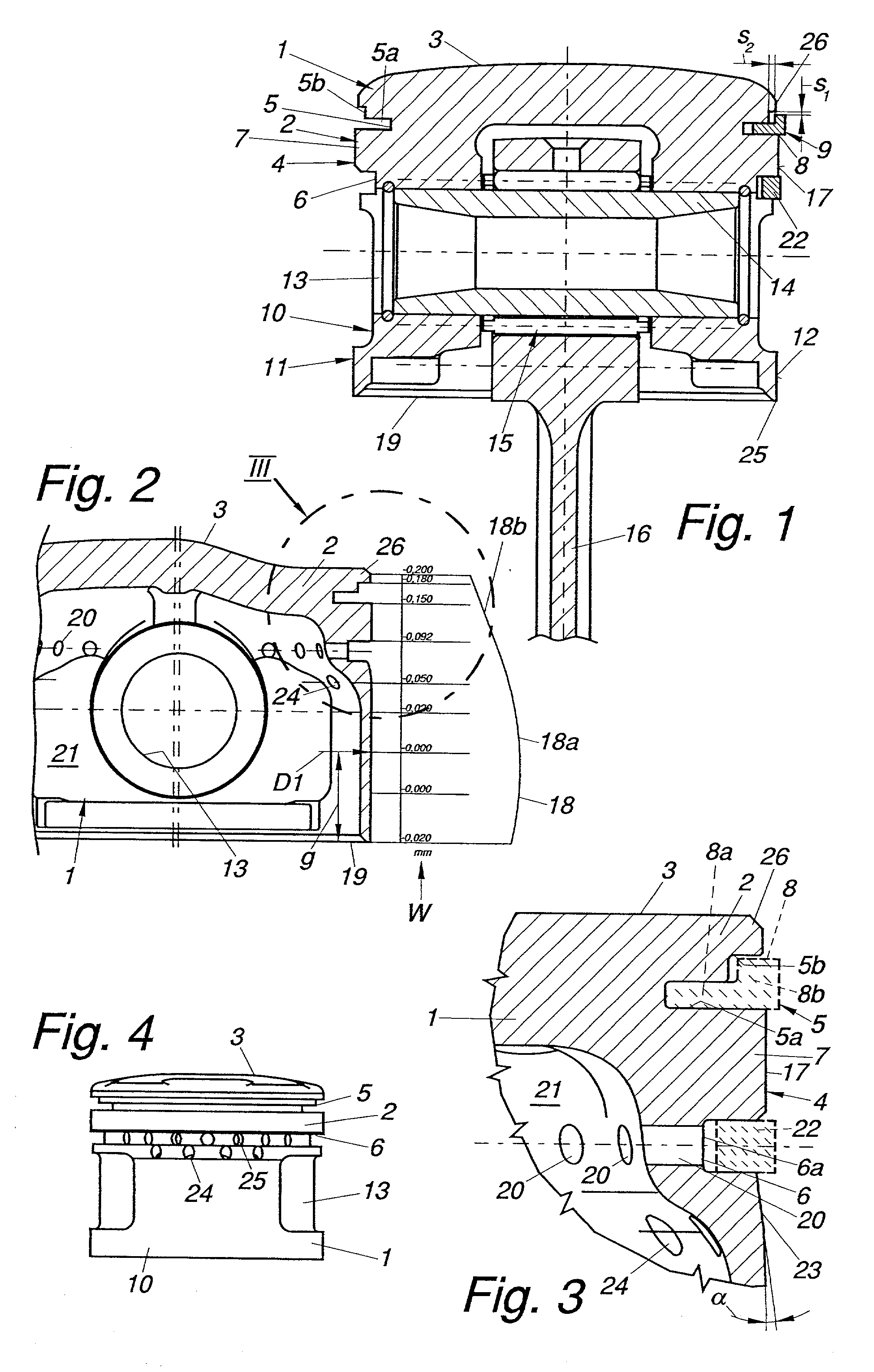
[0014] FIG. 1 is a section through the piston described by the invention along line I-I in FIGS. 5 and 6,

[0015] FIG. 2 is a section through the piston along line II-II in FIG. 5,

[0016] FIG. 3 shows detail III of the piston from FIG. 2,

[0017] FIG. 4 is a side view of the piston,

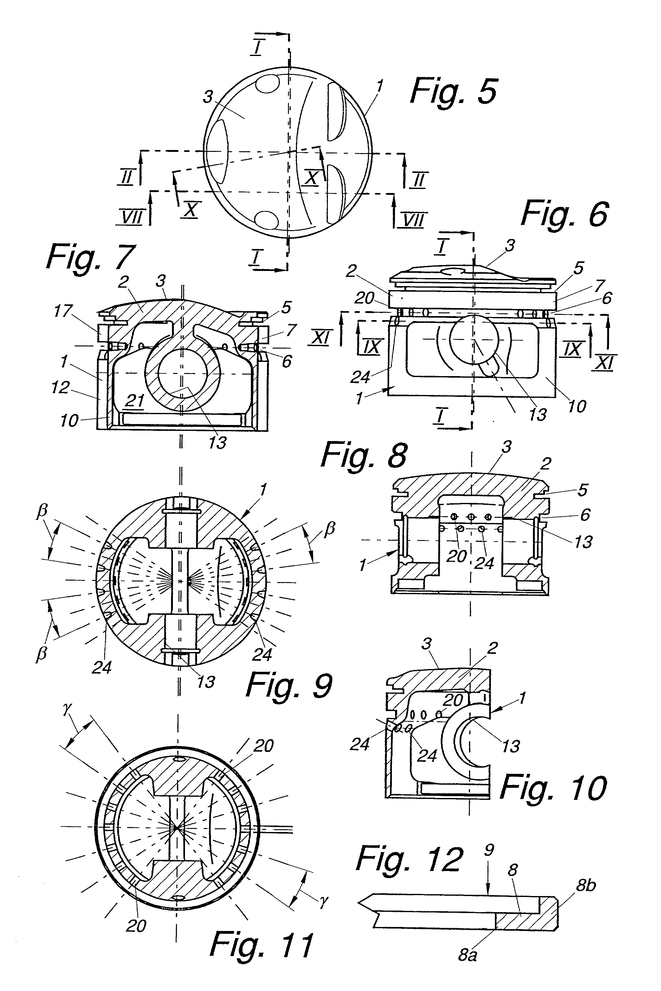
[0018] FIG. 5 is a view of the piston from above,

[0019] FIG. 6 is another side view of the piston in the direction of the axis of the piston pin,

[0020] FIG. 7 is a section through the piston along line VII-VII in FIG. 5,

[0021] FIG. 8 is a section through the piston along line I-I in FIG. 5 and FIG. 6, respectively,

[0022] FIG. 9 is a section through the piston along line IX-IX in FIG. 6,

[0023] FIG. 10 is a section through the piston along line X-X in FIG. 5,

[0024] FIG. 11 is a section through the piston along line XI-XI in FIG. 6, and

[0025] FIG. 12 shows a compression ring of the piston designed as L-ring.

[0026] The piston 1 of a four-stroke internal combusti...


PUM


Abstract

The invention relates to a piston 1 for a four-stroke internal combustion engine, comprising a piston head 2 with a piston top 3 on the side of the combustion space, and a first groove 5 next to the piston top 3 holding a compression ring 9 and a second groove 6 further apart from the piston top 3 holding an oil scraper ring 22 being formed in the wall 4 of the piston head 2, and a piston ring land 7 being formed between the two grooves 5, 6, and further comprising a piston skirt 10 adjacent to the piston head 2, whose wall 11 includes first guide faces 12 for guiding the piston 1 in a cylinder, as well as a piston pin bore 13 carrying a piston pin 14. To reduce oil consumption and diminish frictional losses, it is provided that the ring land 7 between the two grooves 5, 6 be designed as second guide face 17 for guiding the piston 1.

Description

[0001] The invention relates to a piston for a four-stroke internal combustion engine, comprising a piston head with a top face on the side of the combustion space, which will henceforth be referred to as piston top, and a first groove next to the piston top holding a compression ring and a second groove further apart from the piston top holding an oil scraper ring being formed in the wall of the piston head, and a piston ring land being formed between the two grooves, and further comprising a piston skirt adjacent to the piston head, whose wall includes first guide faces for guiding the piston in a cylinder, as well as a piston pin bore carrying the piston pin.[0002] Pistons for four-stroke engines usually have more than two piston rings, to provide for adequate compression in addition to ensuring that enough oil is scraped off the cylinder walls. Piston friction and accompanying losses will increase, however, with the number of piston rings.SUMMARY OF PRIOR ART[0003] In U.S. Pat. ...

Claims


Application Information

Patent Timeline
Patent Type & Authority Applications(United States)
IPC IPC(8): F02F3/00F02F5/00F16J1/02F16J1/04F16J1/08
CPCF02F3/00F05C2201/021
Inventor LAIMBOCK, FRANZ
Owner AVL LIST GMBH
Learn More