Apparatus and process for rapidly filling with hydrogen

a technology of apparatus and hydrogen tank, which is applied in the direction of liquid handling, packaging goods, container discharging methods, etc., can solve the problems of inability to supply hydrogen into the fuel cell, the temperature of the hydrogen tank itself is unduly higher, and the residue of hydrogen is decreased

Inactive Publication Date: 2002-02-07
HONDA MOTOR CO LTD
View PDF0 Cites 78 Cited by
  • Summary
  • Abstract
  • Description
  • Claims
  • Application Information

AI Technical Summary

Benefits of technology

[0019] When the hydrogen filling rate is increased, the amount of heat generated becomes higher accordingly, which increases the range of increasing the temperature within the hydrogen tank. Conversely, if the hydrogen filling rate is decreased, the amount of heat generated becomes lower accordingly, which decreases the range of increasing the temperature within the hydrogen tank. When the pressure within the tank is increased with the progress of the filling the hydrogen tank with hydrogen, the heat generation due to the adiabatic compression is decreased.
[0020] In the apparatus according to the present invention, the tank is filled with hydrogen at a decreased filling rate at the initial filling stage where a large amount of heat is generated, and a filling rate is increased as an amount of heat is decreased. By such a configuration, the heat generation at the initial filling stage where the temperature is easily increased can be suppressed. Also, since a filling rate is increased depending upon the pressure within the tank, even if it takes longer time for increasing the pressure within the hydrogen tank at the initial filling state, the delayed time can be caught up and, the apparatus and the process of the present invention can totally attain a rapidly filling with hydrogen.
[0027] According to this configuration, since the hydrogen is incorporated into the hydrogen tank while restricting the flow amount by the contract means, the increase in the temperature within the hydrogen tank can be suppressed. When the increase in the temperature within the hydrogen tank is suppressed, the filling efficiency can be enhanced, making it possible to fill the hydrogen tank with hydrogen in a rapid manner.
[0036] When the hydrogen filling rate is increased, the amount of heat generated becomes higher accordingly, which increases the range of increasing the temperature within the hydrogen tank. Conversely, if the hydrogen filling rate is decreased, the amount of heat generated becomes lower accordingly, which decreases the range of increasing the temperature within the hydrogen tank. When the pressure within the tank is increased with the progress of the filling the hydrogen tank with hydrogen, the heat generation due to the adiabatic compression is decreased.
[0037] In the process according to the present invention, the tank is filled with hydrogen at a decreased filling rate at the initial filling stage where a large amount of heat is generated, and a filling rate is increased as an amount of heat is decreased. By such a configuration, the heat generation at the initial filling stage where the temperature is easily increased can be suppressed. Also, since a filling rate is increased depending upon the pressure within the tank, even if it takes longer time for increasing the pressure within the hydrogen tank at the initial filling state, the delayed time can be caught up and, the apparatus and the process of the present invention can totally attain a rapidly filling with hydrogen.

Problems solved by technology

If the pressure within the hydrogen tank is decreased, the residue of the hydrogen is decreased accordingly, making it impossible to supply the hydrogen into the fuel cell, etc.
Specifically, unlike the natural gas, no cooling effect takes place in the case of filling with hydrogen even by subjecting hydrogen to expand into the hydrogen tank and, therefore, the temperature of hydrogen filled and the temperature of the hydrogen tank itself become unduly higher.
Increasing the temperature of hydrogen filled and the temperature of the hydrogen tank itself is disadvantageous in terms of causing failure or deterioration of fittings such as PRD (pressure-relief device) and a tank liner, provided on the hydrogen tank and decreasing filling efficiency.

Method used


Image

  • Apparatus and process for rapidly filling with hydrogen
  • Apparatus and process for rapidly filling with hydrogen
  • Apparatus and process for rapidly filling with hydrogen

Examples


Embodiment Construction

[0048] Embodiments and variants of the present invention will now be described by referring to the attached drawings. However, it should be noted that the present invention should not be restricted thereto.

[0049] First, the configuration of the apparatus for rapidly filling a hydrogen tank with hydrogen will now be described.

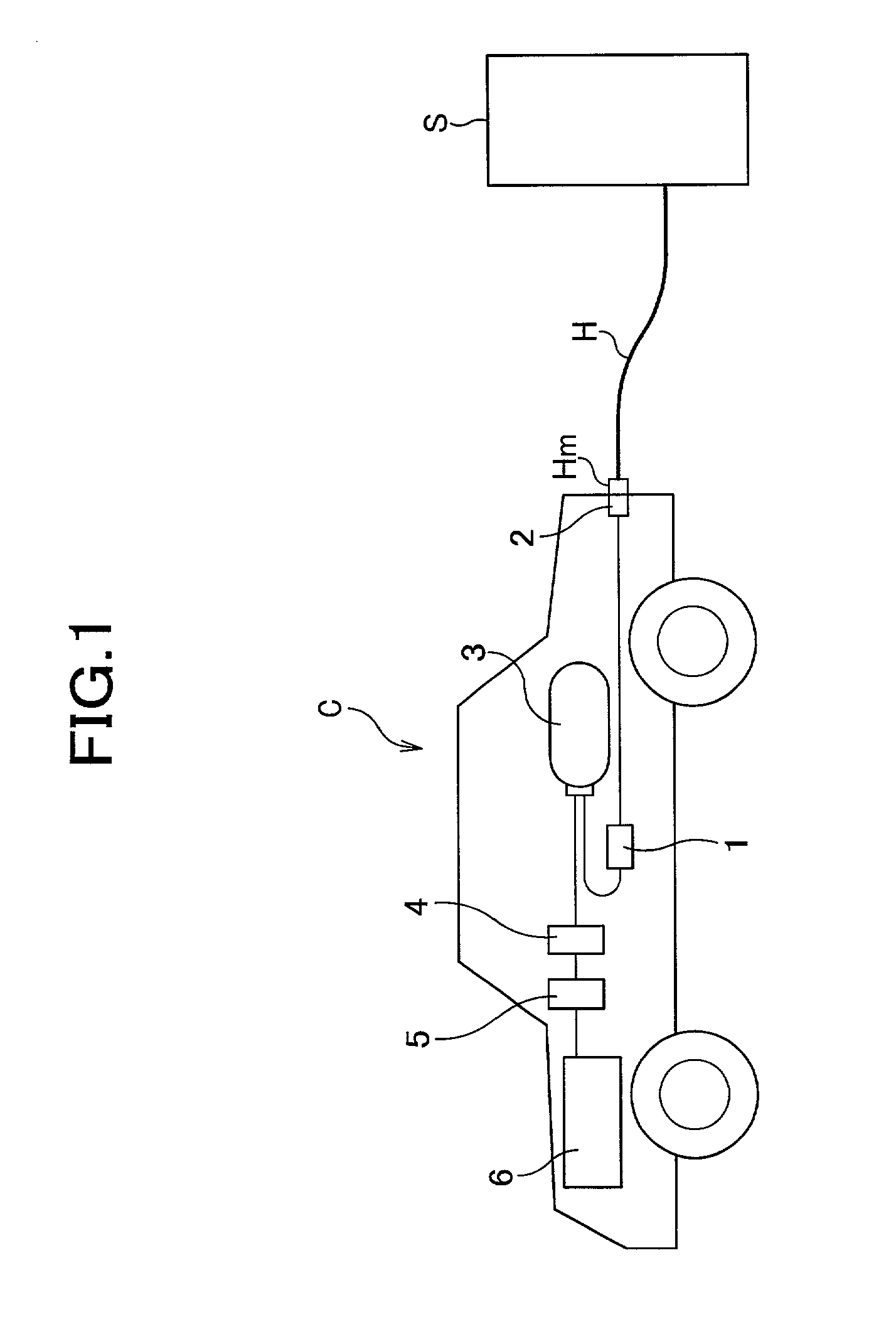
[0050] FIG. 1 is a block diagram showing the configuration for carrying out the process for rapidly filling a hydrogen tank with hydrogen according to the present invention. The configuration of the apparatus according to the present invention is described by referring to FIG. 1.

[0051] A hydrogen source S shown in FIG. 1 is composed of a high temperature compressor and a pressure storage tank, and supplies hydrogen having been compressed to a high pressure of from 25 MPa to 40 MPa into a tank 3, which will be described later on. The hydrogen in the hydrogen source S is pure hydrogen. In order to supply the hydrogen to a vehicle C utilizing the hydrogen as a fuel...


PUM

PropertyMeasurementUnit
Pressureaaaaaaaaaa

Abstract

An apparatus for rapidly filling a hydrogen tank with a hydrogen gas comprises a hydrogen source; a hydrogen tank; a passage which connects the hydrogen source and said hydrogen tank; and a mechanism for varying the hydrogen-filling rate. The mechanism for varying the hydrogen-filling rate changes the hydrogen-filling rate depending upon the pressure within said hydrogen tank. The apparatus can suppress heat generation at the initial filling stage where the temperature is easily increased. Also, even if it takes longer time for increasing the pressure within the hydrogen tank at the initial filling state, the delayed time can be caught up and, the apparatus and the process of the present invention can totally attain a rapidly filling with hydrogen.

Description

BACKGROUND ARTS[0001] 1. Field of the Invention[0002] The present invention relates to an apparatus and process for rapidly filling a hydrogen tank with hydrogen while suppressing exothermic phenomenon during the course of filling.[0003] 2. Description of Related Arts[0004] Recently, from the viewpoint of the expression of the amount of carbon dioxide exhausted, vehicles utilizing hydrogen (H.sub.2) as a fuel, such as fuel cell carried vehicle and hydrogen engine vehicle, have been focused. Such a vehicle carries a hydrogen tank, and the hydrogen having been introduced in the hydrogen tank is supplied into a fuel cell or an engine to generate a drive force.[0005] The hydrogen tank is filled with hydrogen (pure hydrogen) at a pressure of approximately 20 Mpa. The pressure within the hydrogen tank is decreased as the hydrogen is consumed with the fuel cell, etc. If the pressure within the hydrogen tank is decreased, the residue of the hydrogen is decreased accordingly, making it impos...

Claims


Application Information

Patent Timeline
IPC IPC(8): F16K17/30F17C5/00F17C5/06F17C13/04
CPCF16K17/30F17C2270/0184F17C5/06F17C2260/025Y02E60/321F17C2205/0326F17C2205/0382F17C2221/012F17C2223/0123F17C2227/04F17C2250/032F17C2250/043F17C2250/0636F17C2265/065F17C2270/0168F17C5/007Y02E60/32
Inventor TOGASAWA, SHUICHIOTAKA, AKIFUMIYAMADA, AKIRATAKAKU, KOICHI
Owner HONDA MOTOR CO LTD
Why Eureka
Try Eureka