
Pressure vessel head ring assembly

Inactive Publication Date: 2001-12-06
AVMO ACQUISITION LLC NOW KNOWN AS AVIATION MOBILITY
View PDF0 Cites 7 Cited by
  • Summary
  • Abstract
  • Description
  • Claims
  • Application Information

AI Technical Summary

Problems solved by technology

Previous head ring designs, however, often incurred damage in the field.
While previous head ring designs protected the valving to some extent, the head ring itself often deformed from normal use.
Rings were damaged because of these failed welds.
These weld failures shortened the expected life of each head ring and created premature repair costs.
Other problems with these previous head ring designs involved the fastening mechanism.
This U-bolt clamping system, however, could not maintain proper orientation between the head ring and the valving.
The U-bolt clamp also has exposed threads, and these exposed threads were easily damaged during handling.
These damaged threads make the U-bolt difficult to remove.
The U-bolt clamping system is also labor intensive and requires an intricate field operation.
Prior head ring designs also had compatibility problems.
While there are two leading manufacturers of light-weight gas cylinders, there are slight dimensional differences between each manufacturer's cylinder design.
Previous head ring designs were not compatible with both manufacturers.
This compatibility problem increased the cost of the head ring and created confusion and mismatch.
While both Luxfer and Catalina manufacture pressure vessels, there are dimensional differences between each manufacturer's design.

Method used


Image

  • Pressure vessel head ring assembly
  • Pressure vessel head ring assembly
  • Pressure vessel head ring assembly

Examples


Embodiment Construction

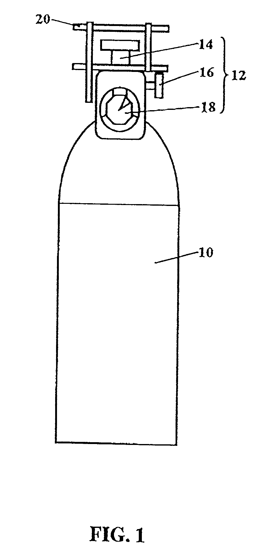
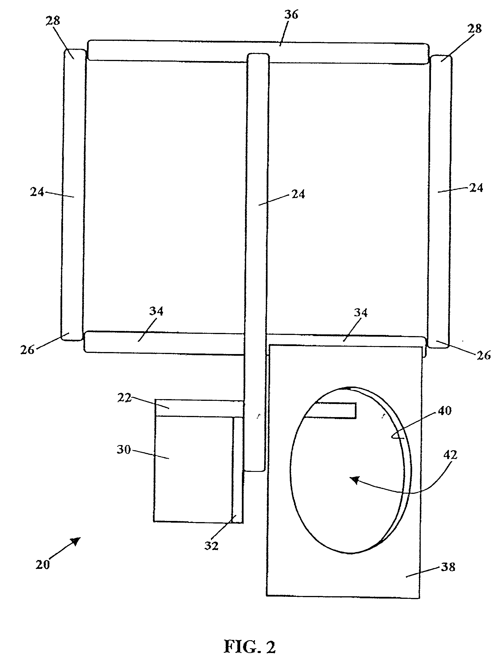
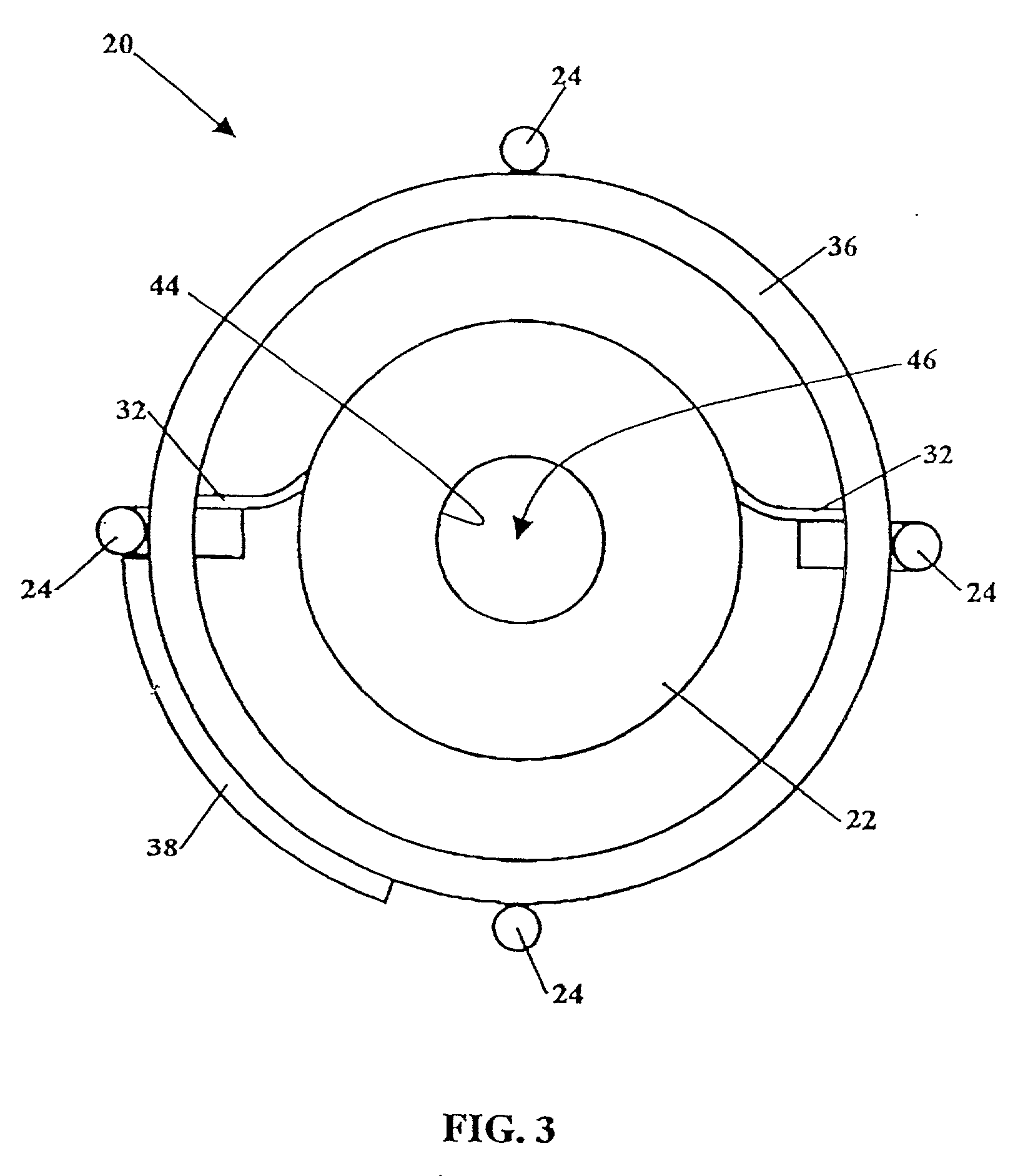
[0034] One embodiment of the head ring 20 is further illustrated by the following non-limiting example. This particular non-limiting example of the head ring 20 is sized for oxygen dispensing pressure vessels used in the airline industry. While this example is sized for use in the airline industry, the dimensions given below may vary for other applications. The head ring 20 shown in FIGS. 1-4, and further shown in FIGS. 6-8 , has an overall height 70 (FIG. 6) in the range of about 5 inches to about 8 inches, preferably in the range of about 6 inches to about 7 inches, to protect the valving assembly 12. In particular, the head ring 20 protects the regulator 14, which is a compact regulator design such as part number 165408DA produced by Precision Medical, Inc. or part number CP540-8UNBR-SH produced by Contemporary Products, Inc. The first ring 34 and the second ring 36 each have an outer diameter 72 (FIG. 7) in the range of about 3 inches to about 5 inches. The first ring 34 and the...


PUM


Abstract

A head ring protects the valving assembly, or regulator, flow adjuster, and content gauge, commonly attached to a pressure vessel, such as a conventional pressurized gas cylinder. The head ring includes a base securable to the dispensing end of the pressure vessel. A plurality of posts are distributed about a perimeter of the base, each of the posts extending vertically upward from about the base to beyond the valving assembly. Each of the posts has a first end and a second end. A collar is secured to a portion of the perimeter of the base, and the collar extends vertically downward from the perimeter of the base. The collar includes a radially-extending flange at each end. A first ring horizontally extends from the posts and is secured adjacent to the first end of the posts. A second ring horizontally extends from the posts and is secured adjacent to the second end of the posts. The first ring and the second ring are radially positioned outward of the regulator, the flow adjuster and the content gauge. A gauge protection plate extends vertically downward from the first ring. The gauge protection plate includes an interior wall defining a plate opening. The plate opening is sized to allow visual access to the content gauge. The head ring protects the valving assembly during handling and transport of the pressure vessel. The head ring assembly may also act as part of a pressure vessel assembly or a package assembly, the package assembly including an outer pack made from a durable material defining a bag sized to surround and protect the pressure vessel.

Description

[0001] This application claims the benefit of U.S. Provisional Application No. 60 / 196,358, filed Apr. 12, 2000.[0002] 1. Field of the Invention[0003] This invention relates generally to pressure vessels, such as pressurized gas canisters and compressed gas cylinders, and, more particularly, to a head ring assembly for protecting the valving of pressure vessels.[0004] 2. Description of the Related Art[0005] The Air Transport Association ("ATA") and the International Air Transport Association ("IATA") have recently released specifications affecting the design of airline shipping containers. Specifications ATA-300 and IATA-200 establish the airline industry's standards for acceptable packaging of shipping containers used in air transport and address such issues as proper packaging design, marking, and inspection / testing. These specifications ensure that materials, such as pressurized cylinders containing oxygen and other fluids, are adequately protected during handling and transport. F...

Claims


Application Information

Patent Timeline
IPC IPC(8): F17C13/04F17C13/06F17C13/08
CPCF17C13/04F17C13/06F17C13/084F17C2201/0119F17C2201/058F17C2203/0646F17C2205/0165F17C2205/0308F17C2205/0323F17C2205/0338F17C2221/011F17C2221/014F17C2221/035F17C2223/0153F17C2223/033F17C2270/0709F17C2270/0745
Inventor CARLO, CHARLES C.MAULDIN, STEPHEN H.
Owner AVMO ACQUISITION LLC NOW KNOWN AS AVIATION MOBILITY
Learn More