Method of mounting a pneumatic radial tire

a radial tire and pneumatic technology, applied in the field of pneumatic radial tires, can solve the problems of insufficient balance of rigidity, ground contact property and generation of lateral force in the tire, and convergence of vibration behavior in the vehicle body,

Inactive Publication Date: 2001-11-29
BRIDGESTONE CORP
View PDF4 Cites 8 Cited by
  • Summary
  • Abstract
  • Description
  • Claims
  • Application Information

AI Technical Summary

Benefits of technology

[0010] The action of the above mounting method is described below. That is, when the above tire is mounted on a front wheel of a vehicle such as motorcycle or the like, the pair of the cross belt members in the tire are arranged so as to finally contact a portion of the cord in the belt member facing the opening space with ground in a forward rotating direction of the tire. Thus, the inclinations of the cords in the cross belt members are so-called inverted herringbone form that the portion of the cord in the belt member facing to the opening space finally contact with ground in the forward running direction of the tire or a positive rotating direction thereof. Therefore, by mounting the above tire as a front tire so as to render the cord inclinations in the pair of the cross belt members into the inverted herringbone form, the deformation and resistance force of the tire are made optimum against external force acting to the front tire.
[0012] The action of the above mounting method is described below. That is, when the above tire is mounted onto a rear wheel of a vehicle such as motorcycle or the like, the pair of the cross belt members in the tire are arranged so as to firstly contact a portion of the cord in the belt member facing the opening space with ground in a forward rotating direction of the tire. Thus, the inclinations of the cords in the cross belt members are so-called herringbone form that the portion of the cord in the belt member facing to the opening space firstly contact with ground in the forward running direction of the tire or a positive rotating direction thereof. Therefore, by mounting the above tire as a rear tire so as to render the cord inclinations in the pair of the cross belt members into the herringbone form, the deformation and resistance force of the tire are made optimum against external force acting to the rear tire.
[0013] According to a third aspect of the invention, there is the provision of in a method of mounting a pneumatic radial tire comprising a spiral belt formed by spirally winding a cord along a circumferential direction of a crown portion of the tire, and a pair of cross belt members arranged in parallel to each other at both sides of an equatorial plane of the tire and at a given opening space, cords of which members being extended at a given cord angle in opposite directions to each other with respect to the equatorial plane, an improvement wherein the tire is mounted as a front tire such that the pair of cross belt members are arranged so as to finally contact a portion of the cord in the belt member facing the opening space with ground in a forward rotating direction of the tire and another tire is mounted as a rear tire such that the pair of cross belt members are arranged so as to firstly contact a portion of the cord in the belt member facing the opening space with ground in a forward rotating direction of the tire.
[0015] That is, by adopting the above mounting method, the rigidity required as the tire can effectively be ensured with respect to input of the external forces to the radial direction and lateral direction of the tire acting to the front and rear tires at each state of the straight running and the cornering. And also, the external force acting to the front wheel in the braking and the external force acting to the rear wheel in the traction differ with each other in the input direction of the external force, but by making the cord inclinations of the belt members in the front tire opposite to those in the rear tire can effectively be ensured the rigidity required as the tire against these external forces.
[0016] In a preferable embodiment of the invention, a steel cord having an initial tensile strength of no less than 50 cN / cord is used in any one of the spiral belt and the pair of the cross belt members. That is, when the steel cords having an initial tensile strength of no less than 50 cN / cord are applied to any one of the spiral belt and the cross belt member, the rigidity required as the tire can effectively be ensured and is possible to cope with external forces applied from various directions.
[0017] In a further preferable embodiment of the invention, a organic fiber cord having an initial tensile strength of no less than 50 cN / cord is used in any one of the spiral belt and the pair of the cross belt members. That is, when the organic fiber cords having an initial tensile strength of no less than 50 cN / cord are applied to any one of the spiral belt and the cross belt member, the rigidity required as the tire can effectively be ensured and is possible to cope with external forces applied from various directions.

Problems solved by technology

However, when the radial tire having the spiral belt and the pair of cross belt members is mounted onto either the front wheel or the rear wheel of the motorcycle, there is no technique that an angle of the cord in the cross belt member is clearly defined with respect to each of the front and rear tires.
In each of the conventional front and rear tires, therefore, the balance of rigidity, ground contact property and generation of lateral force in the tire is not satisfactorily achieved.
To this end, the above tires have a drawback that convergence of vibration behavior in a vehicle body as a whole, running performances including cornering force at a corner, gripping limit and slip controlling property are not obtained at sufficiently high levels, respectively.
That is, when the angle of the cord constituting each cross belt member with respect to the equatorial plane exceeds 80.degree., the rigidity as the tire is not sufficiently ensured, while when the angle is less than 20.degree., the step difference of the rigidity between the presence and the absence of the cross belt member pair becomes too large and the linear property of cornering force with respect to the camber angle is damaged.
Furthermore, when the width of the opening space between the pair of cross belt members is less than 1 mm, the opening space is too small and the bending rigidity in the vicinity of the center of the crown portion becomes too high, so that the ride comfort is degraded.
While, when the width of the opening space exceeds 50 mm, the effect of ensuring the rigidity required as the tire is substantially lost.
To this end, the rigidity required as the tire can not be ensured, so that the deformation of the tire becomes large to increase the posture change of the vehicle body, and also the slipping controllability can not sufficiently be ensured.
When the total width A is less than 70% of the tread width B, the rigidity required as the tire can not be ensured, while when the total width A exceeds 150% of the tread width B, the rigidity of the tire becomes too high, so that the degradation of the vibration absorptivity occurs.

Method used


Image

  • Method of mounting a pneumatic radial tire
  • Method of mounting a pneumatic radial tire
  • Method of mounting a pneumatic radial tire

Examples


Embodiment Construction

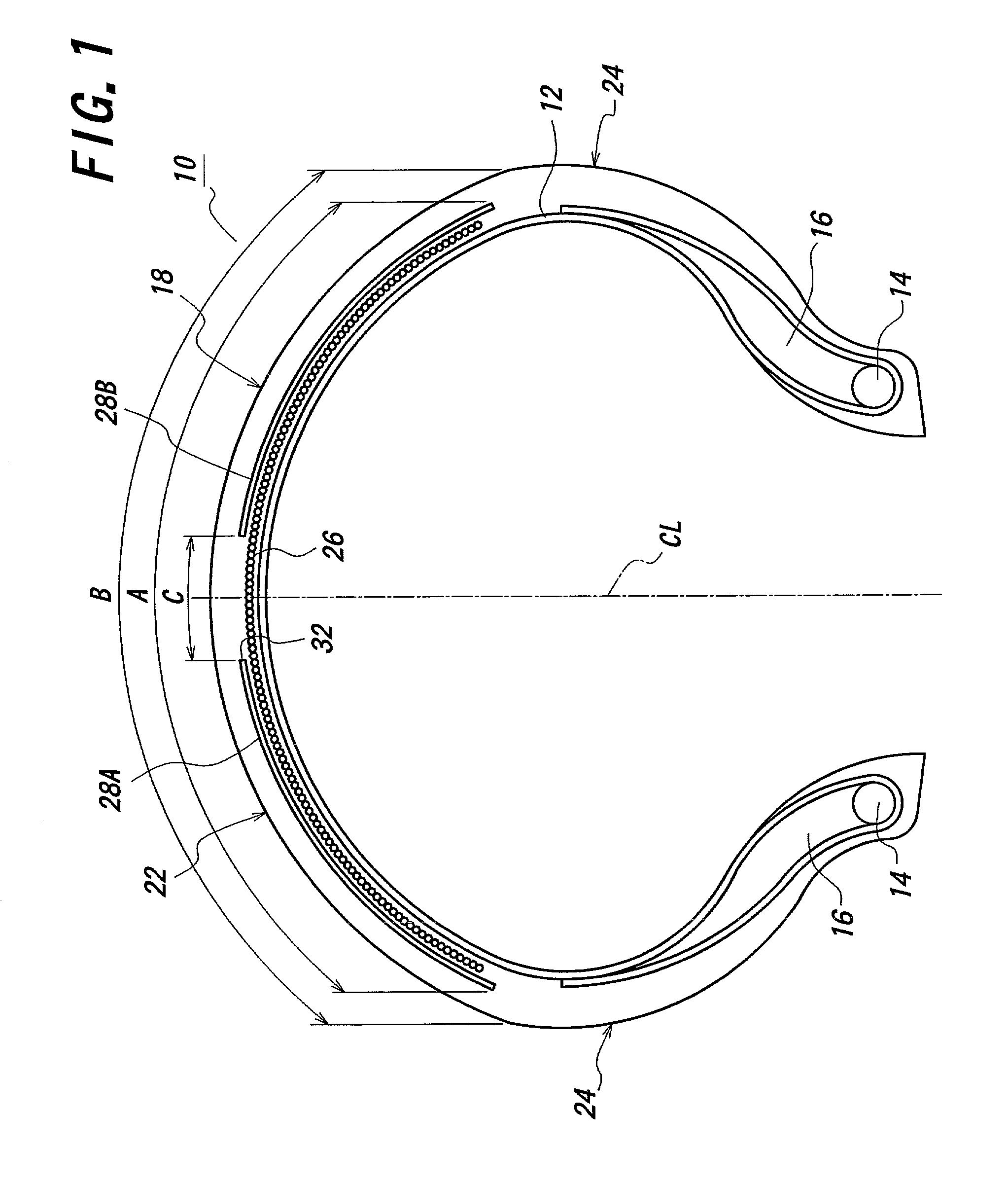
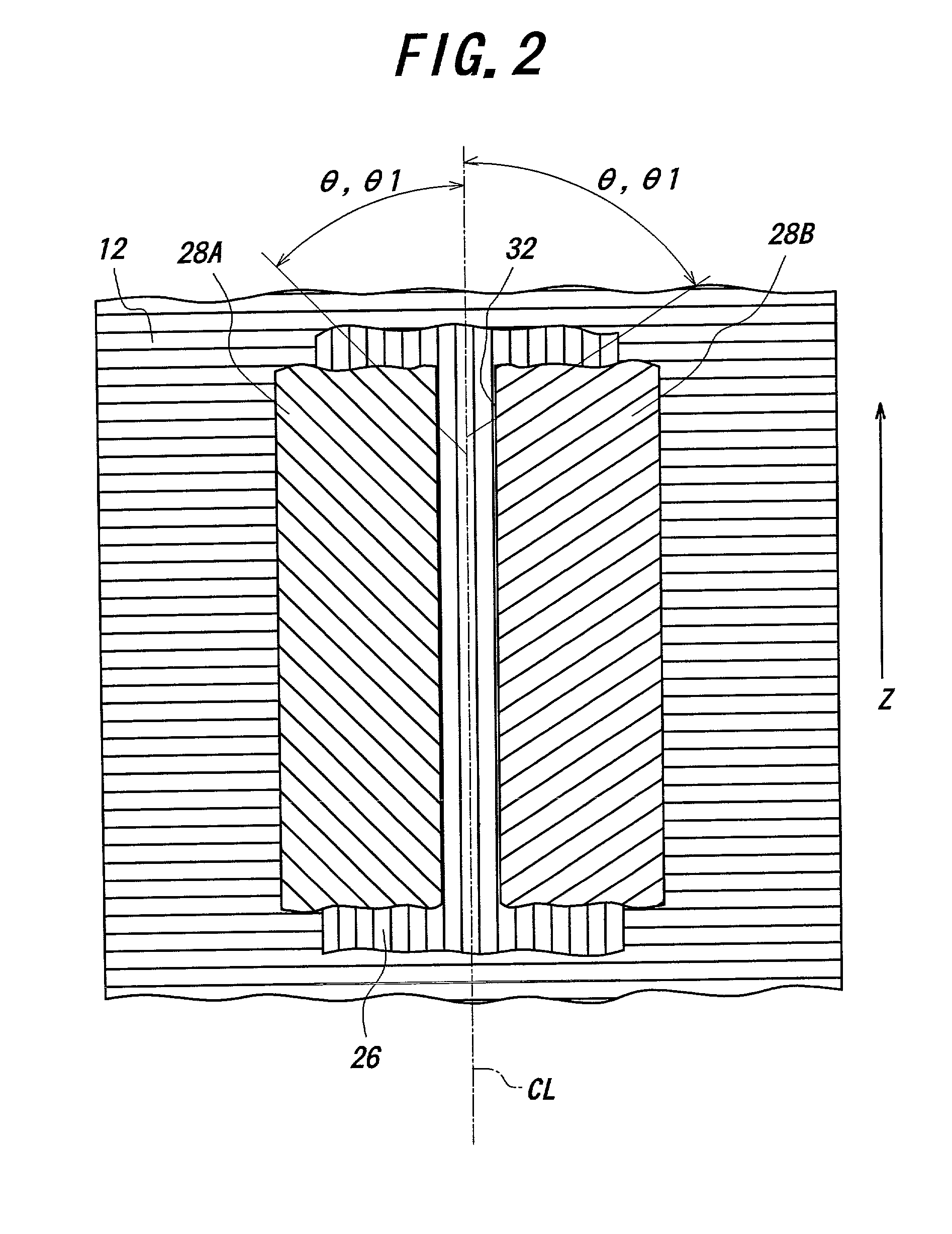
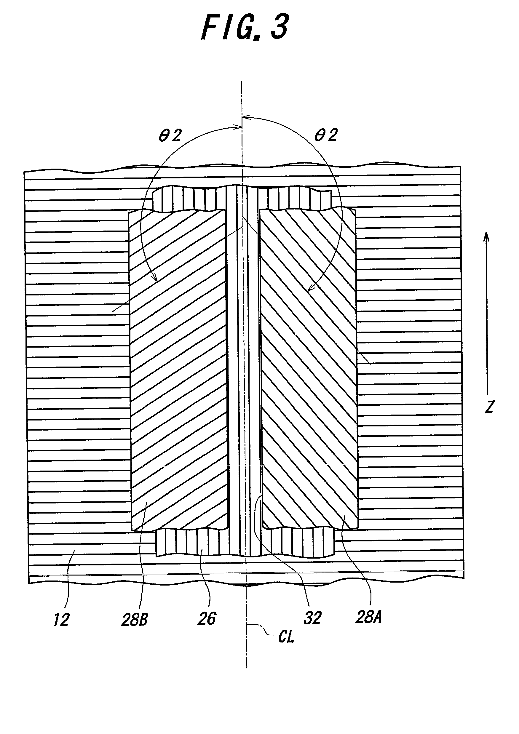
uses the pneumatic radial tire 10 described in the first embodiment and Example 2 uses the pneumatic radial tire 10 described in the second embodiment. For the comparison, the conventional example uses a tire with a belt structure having no pair of cross belt members 28A, 28B and the comparative example uses a tire having a spiral belt 26 and a pair of cross belt members 28A, 28B except that the cord inclination in the pair of the cross belt members takes a herringbone form in a front tire and an inverted herringbone form in a rear tire. With respect to these examples, the actual running test is carried out to obtain results as shown in Table 1.

1 TABLE 1 Corner gripping High-Handling Grip- Slipping speed Quick Neutral ping control- stability Shimmy response property limit lability Conventional 100 100 100 100 100 100 Example Comparative 110 110 110 100 105 105 Example Example 1 130 120 130 120 120 120 Example 2 120 120 120 110 110 110

[0063] The evaluation by the actual running test ...


PUM

PropertyMeasurementUnit
widthaaaaaaaaaa
angleaaaaaaaaaa
widthaaaaaaaaaa

Abstract

In the method of mounting a pneumatic radial tire comprising a spiral belt and a pair of cross belt members arranged in parallel to each other at both sides of an equatorial plane of the tire and at a given opening space onto a vehicle body, the tire is mounted as a front tire and / or a rear tire so as to contact a portion of the cord in the belt member facing the opening space with ground under a given condition in a forward rotating direction of the tire.

Description

[0001] 1. Field of the Invention[0002] This invention relates to a pneumatic radial tire capable of making optimum a deformation and a resistance force of the tire in correspondence to a difference between external forces respectively acting to a front tire and a rear tire and more particularly to a method of mounting a pneumatic radial tire suitable for use in motorcycles and the like.[0003] 2. Description of Related Art[0004] There have hitherto been known various structures as a pneumatic tire for a vehicle such as motorcycles and the like. With the maintenance of recent expressways, it is required to ensure a high-speed durability even in pneumatic radial tires for motorcycles. For this end, there are also known tires having a spiral belt extending in a circumferential direction of a crown portion thereof.[0005] And also, there are known a mounting structure that tires having only a spiral belt are mounted onto a front wheel and a rear wheel of a motorcycle, respectively, and a ...

Claims


Application Information

Patent Timeline
Patent Type & Authority Applications(United States)
IPC IPC(8): B60C5/00B60C9/18B60C9/20B60C9/22B60C19/00
CPCB60C9/2009B60C9/2204B60C19/001Y10T29/49826B60C2009/2041Y10T152/10801Y10T152/10765Y10S152/904
Inventor NAKAMURA, TSUTOMU
Owner BRIDGESTONE CORP
Why Eureka
Try Eureka