
Medical anesthetic needle

a technology of anesthetic needles and needles, which is applied in the direction of guide needles, infusion needles, catheters, etc., can solve the problems of patient pain when needled, insufficient pain relief, and patients often feeling pain when needled

Inactive Publication Date: 2001-11-15
DR JAPAN
View PDF0 Cites 71 Cited by
  • Summary
  • Abstract
  • Description
  • Claims
  • Application Information

AI Technical Summary

Problems solved by technology

The fore-end part of the outer needle was deburred, but relatively sharp, therefore resulting in patients often feeling pain when needled.
However, the extent of its pain easing was not enough.
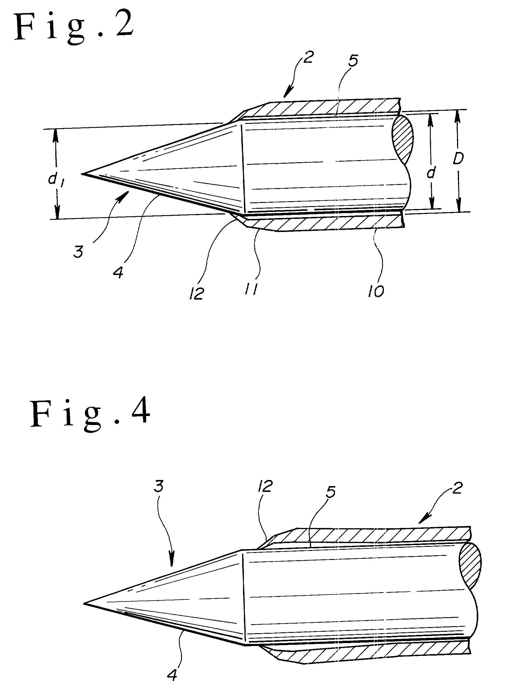
The cause of a patient feeling pain when needled, even though the fore-end part of the tubular outer needle is formed round, is a gap between the fore-end section of its outer needle and its inner needle.
When a patient's nervous tissue is nipped in this gap, the patient feels pain.

Method used


Image

  • Medical anesthetic needle
  • Medical anesthetic needle
  • Medical anesthetic needle

Examples


Embodiment Construction

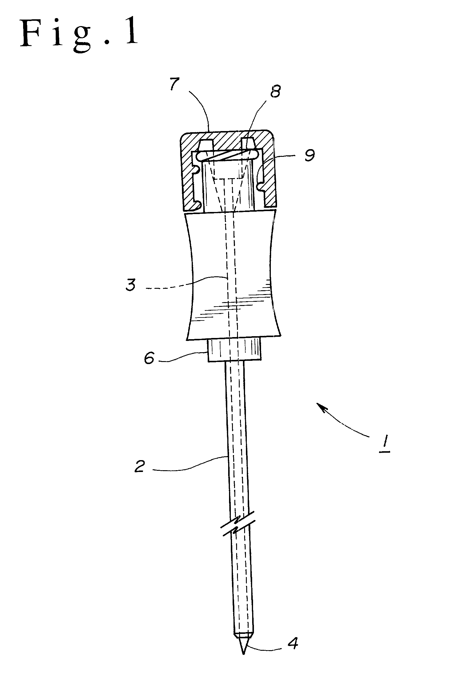
[0013] As shown in FIG. 1, an anesthetic needle 1 includes a hollow outer needle 2 made of stainless steel tube and a solid inner needle 3 made of stainless steel bar. The rear end of the outer needle 2 is fixed to a needle base 6. The inner needle 3 is inserted through a needle hole of the needle base 6 into the outer needle 2. A tip 4 of the inner needle 3 that protrudes from the fore end of the outer needle 2 is of a pencil-pointed shape, i.e., a conical shape. A cap 7 is fixed to the rear end of the inner needle 3, where a spiral-shaped female screw part 9 is formed on the internal circumferential surface of the cap 7. A spiral-shaped male screw part 8 that engage's with the female screw part 9 of the cap 7, is disposed on a section protruding from the rear end of the needle base 6. When inserting the anesthetic needle, the male screw part 8 is screwed into the female screw part 9 to the limit, to define the axial limit position of the inner needle 3 relative to the outer needle...


PUM


Abstract

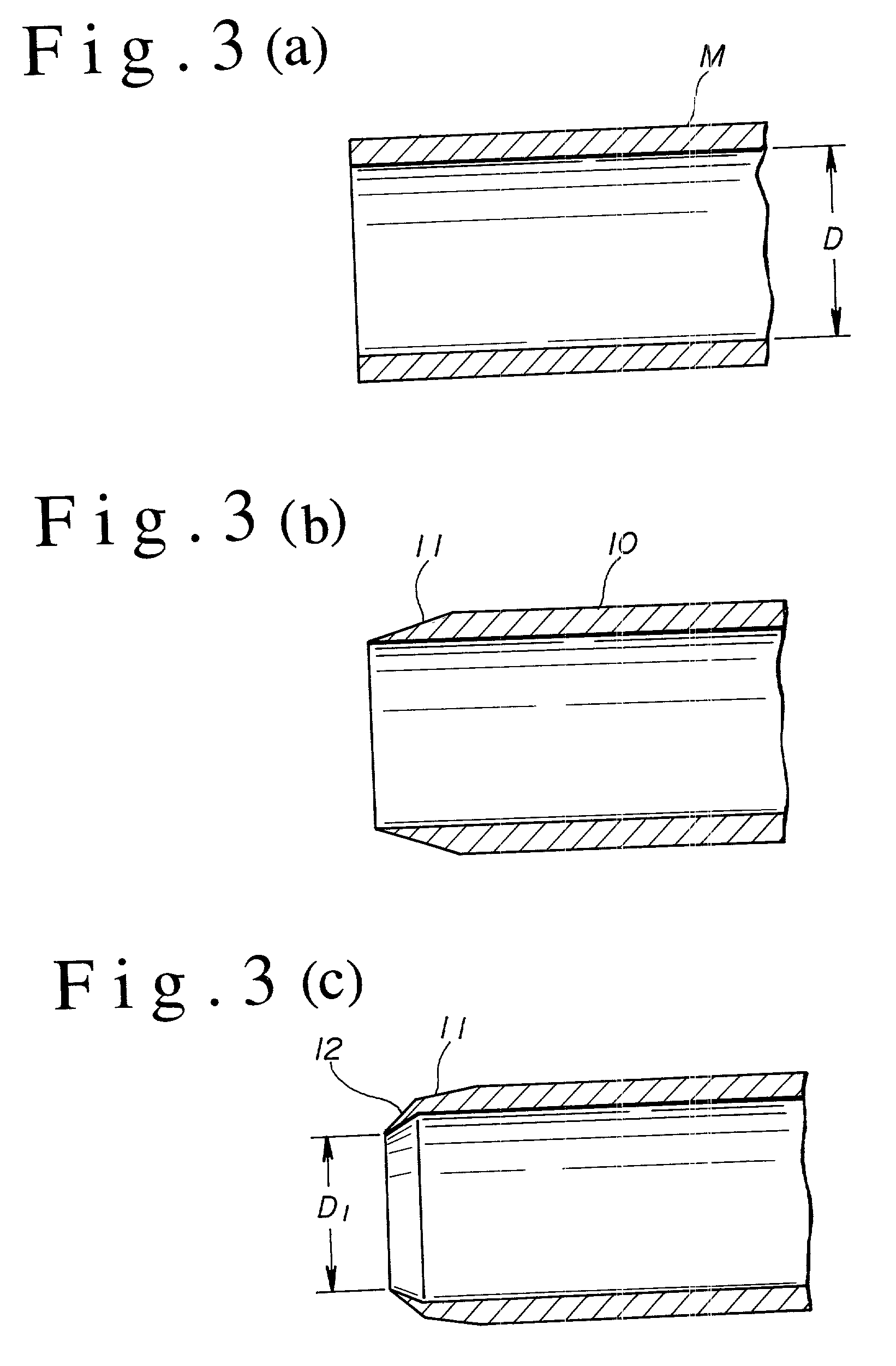
A medical anesthetic needle (1) is provided that includes an inner needle (3) of a straight needle shape, having a pencil-pointed tip (4), and an outer needle (2) of a straight tubular shape, having the inner needle inserted thereinto and therethrough from the rear end thereof. A foremost-end part (12) of a hollow, truncated conical shape or the like of the outer needle (2) is formed so that the minimum inner diameter thereof is smaller than the outer diameter of the main body (5) of the inner needle (3). When the inner needle (3) is inserted into and through the outer needle (2), the circumferential fore-end edge of the foremost-end part (12) is in close contact with the circumferential surface of the tip (4) or the main body (5) of the inner needle (3), and no gaps are thus formed therebetween. Therefore, when needled, a patient's nervous tissue is unlikely to be nipped in a gap between the inner and outer needles to cause pain to the patient.

Description

[0001] The present invention relates to a medical anesthetic needle including an inner needle, having a pencil-pointed tip, and a tubular outer needle, having the inner needle inserted thereinto and therethrough.BACKGROUND TECHNOLOGY[0002] Conventional inner needles, having a pencil-pointed tip (4), of anesthetic needles, were inserted into and through a straight-tubular outer needle having its fore-end section formed in a tapered shape tapering off towards the end thereof, i.e., a hollow, truncated conical shape. The fore-end part of the outer needle was deburred, but relatively sharp, therefore resulting in patients often feeling pain when needled. An anesthetic needle for easing such pain is disclosed in Japanese Utility Model No. 3018360 where the fore-end section of a tubular outer needle has the edge formed round on the right-angled cut fore-end face thereof[0003] With an anesthetic needle with the fore-end section of a tubular outer needle thereof having the edge formed round...

Claims


Application Information

Patent Timeline
IPC IPC(8): A61M25/06
CPCA61M25/06
Inventor HIGUCHI, AKIOHYUGAJI, HAYATO
Owner DR JAPAN
Learn More