Bender stand

Inactive Publication Date: 2001-10-25
GODIN JEFFREY
View PDF0 Cites 3 Cited by
  • Summary
  • Abstract
  • Description
  • Claims
  • Application Information

AI Technical Summary

Benefits of technology

[0013] These and other objects are achieved with the present invention, which is a stand for use with a hand bender of selectable angle type. The assistive bender stand includes a bender securing assembly and a base that provides the foundation and, when necessary, leverage, to bend conduit, pipe, or tube, as desired. The combination of the bender securing assembly and the base, which may optionally be of adjustable dimensions, enables a user to leverage the capability of an inexpensive hand bender into formation of accurate bends. Moreover, the securing assembly and base combination firmly fixes the handle portion of the bender in a stationary position not subject to random movements of the user.
[0018] The combination of the securing frame and the support frame of the present invention provide a convenient stand that allows a user to greatly increase the capabilities of a relatively inexpensive hand bender. In particular, the user need only obtain the stand of the present invention and one or more hand benders of selectable head angles to create a mechanical hand bending system that is portable and therefore usable for a variety of applications. In addition, combining the present stand device with a hand bender and a conduit level such as The Eliminator.TM. offered by Bending Technologies, Inc. of Fairfield, Me., ensures easy and accurate bend formation. This is achieved without the expense, complexity, and other noted limitations associated with an automated bender. Further, the assistive bender stand of the present invention is easily portable by a single individual and may be conveniently stowed in a secure location on site.

Problems solved by technology

Conduit benders are particularly useful in the electrical trades for establishing runs through which wiring is passed without kinking, getting snagged, or generally having an unsightly appearance when the conduit is applied to exterior walls.
The hand bender is limited in that it can only produce one bend angle, the most common being a 90.degree. bend.
Unfortunately, the user may wish to bend the conduit at other angles and so is required to purchase benders having differing recess curves.
Further, hand benders are limited in that they can only be used to create, at least easily, a single bend in the conduit.
However, hand benders cannot be used to establish multiple bends in a single run without going through significant contortions.
This can be a time consuming and frustrating process that may require experimentation and unacceptable conduit shape.
All of this can lead to increased cost for a particular project, even when using a low-cost hand bender.
Further, it is likely to reduce the time required to form conduit with multiple bends.
Nevertheless, the cost of automated benders is seen to be cost prohibitive for many tradespeople.
In addition, for the individual tradesperson, an automated bender is generally not sufficiently portable to enable a single person to maneuver it from one job site to another.
Unfortunately, they appear to be too large to conveniently stow away in a secured location on a job site (such as a lockbox), but not so big that they cannot be pilfered.
The mechanical benders presently available are bulky, hard to operate, and difficult to transport easily.
For that reason, they tend to be permanent-type fixtures not generally suited for the individual having his or her own bending equipment to be moved from one job to another.
There are often situations where the user may not have easy access to an electrical supply, thereby making such a bender ineffective at remote or non-supplied sites.
Further, such relatively complex systems are prone to failures that may require periodic expected and unexpected costly maintenance, driving the real price of the device much higher than the original purchase price.
U.S. Pat. No. 3,949,584 issued to Pearson et al. describes a similar type of automated bender and therefore has similar limitations associated generally with such automated systems.
However, in that situation, after the first shaping of the conduit, it is not possible to make a second opposing bend, for example.

Method used


Image

  • Bender stand
  • Bender stand
  • Bender stand

Examples


Embodiment Construction

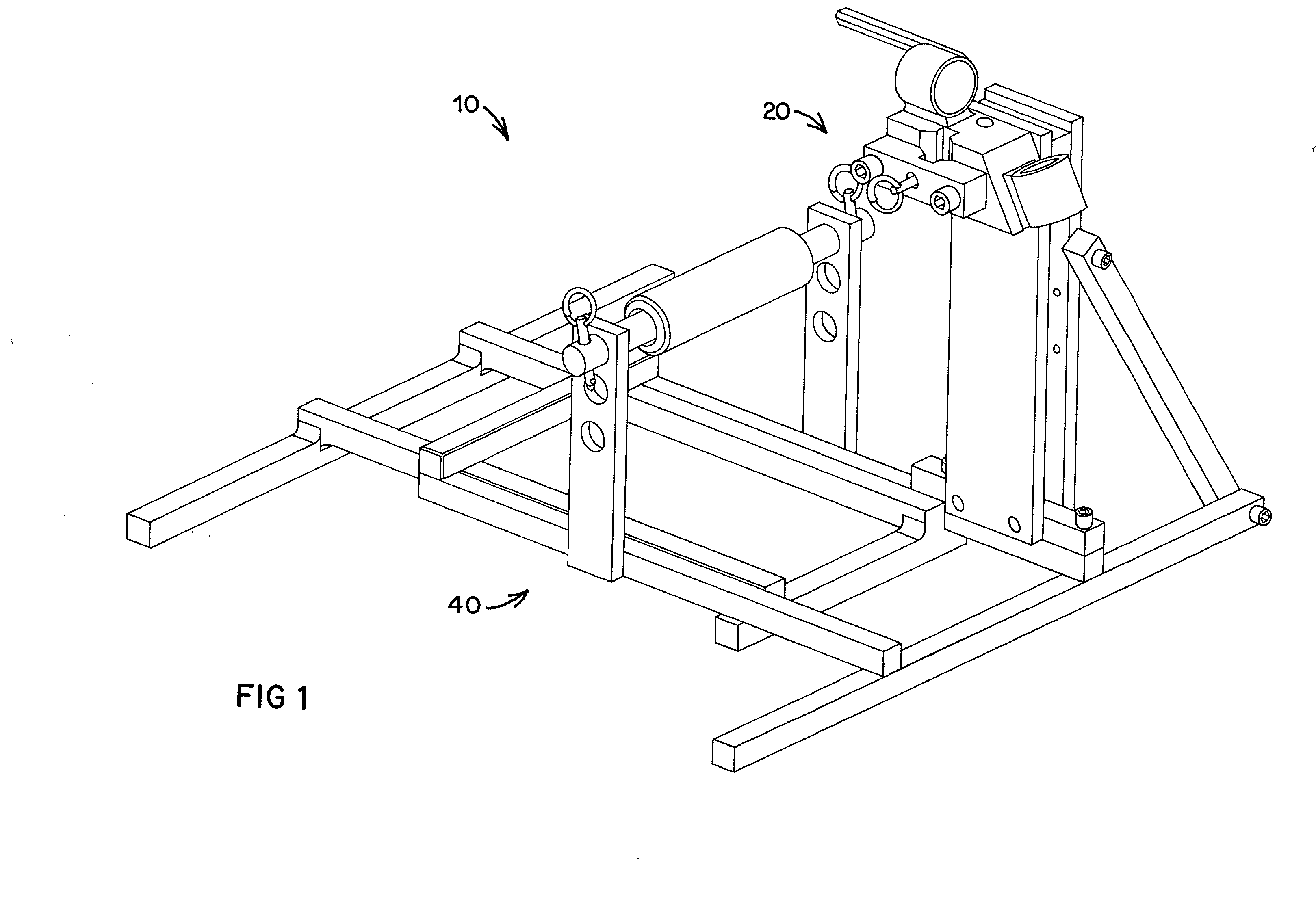
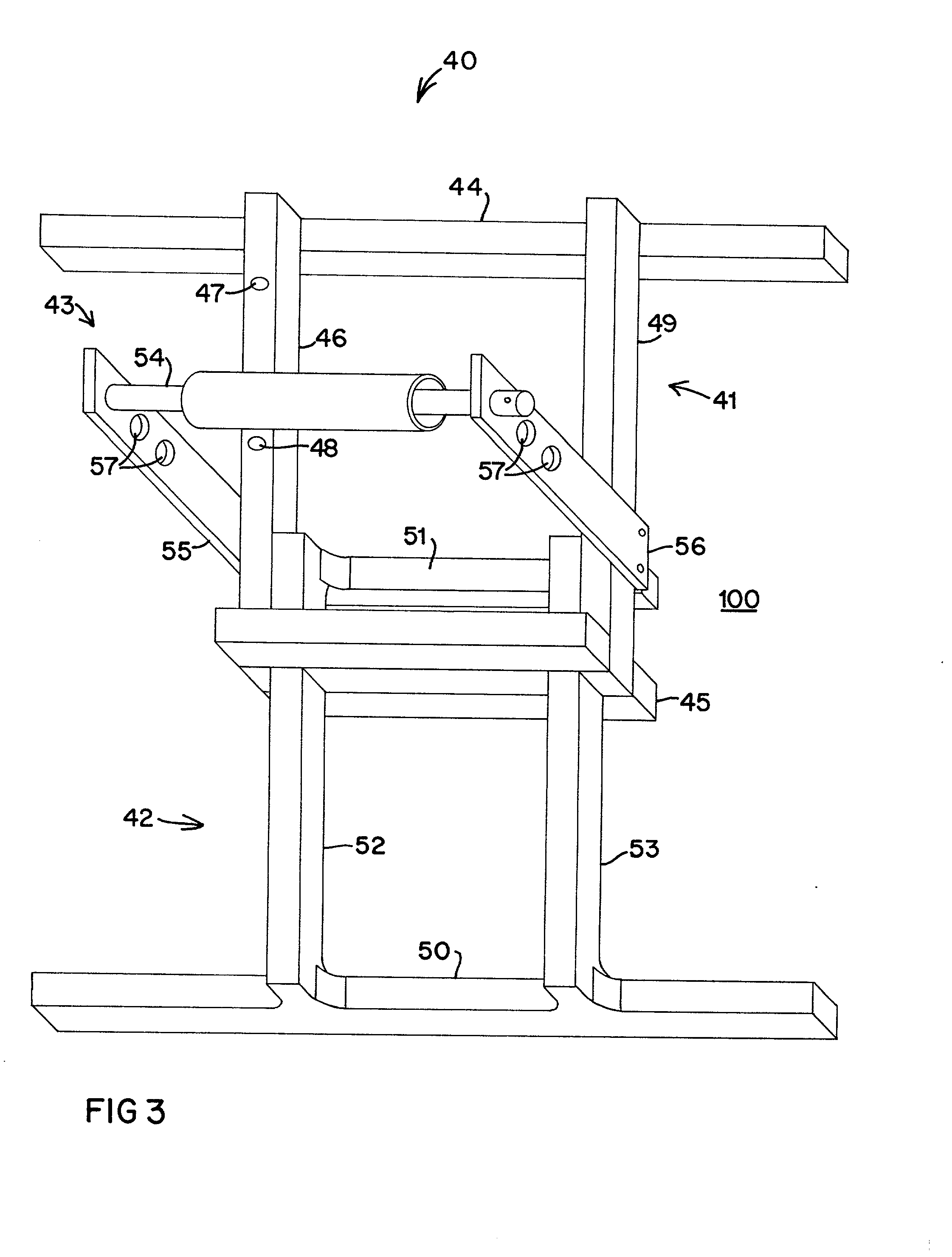
[0023] A bender stand 10 of the present invention is shown in FIG. 1 and includes a bender securing assembly 20 and a base 40. In addition, details of the bender securing assembly 20 are shown in FIG. 2 and details of the base 40 are shown in FIG. 3. The bender stand 10 includes the bender securing assembly 20 connected to the base 40 so that a user may conveniently bend conduit using a hand bender and without jury-rigging a support to keep the conduit in position for accurate bending.

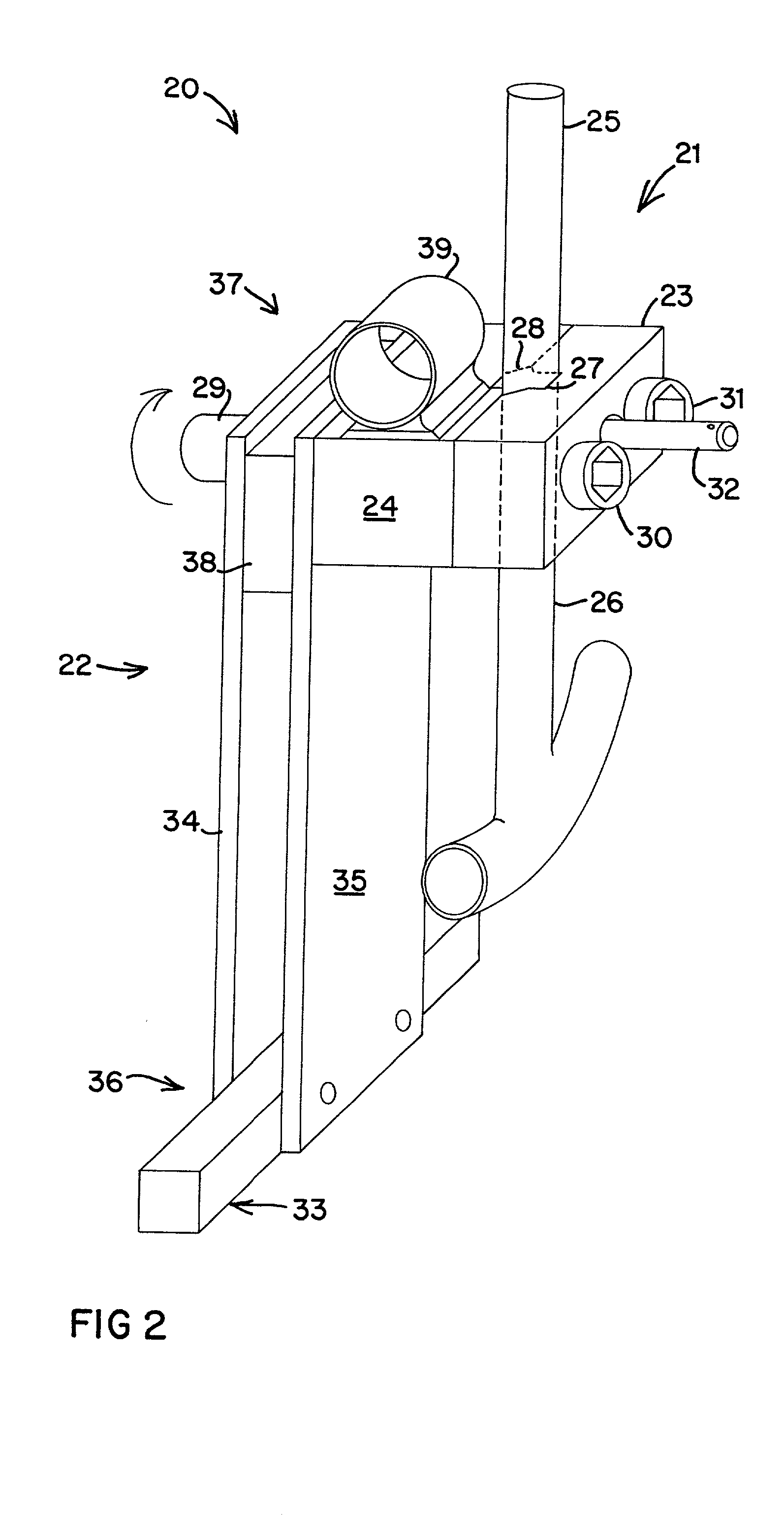
[0024] With reference to FIG. 2, the securing assembly 20 includes a rotatable bender securing frame 21 and a support frame 22. The securing frame 21 includes a first securing block 23 and a second securing block 24 for securing a handle 25 of a hand bender 26 therebetween. The first securing block 23 preferably includes a first V-notch 27 and the second securing block 24 preferably includes a second V-notch 28 therein for fixing the position of the handle 25 once the bender 26 is positioned at a desir...


PUM

PropertyMeasurementUnit
Heightaaaaaaaaaa
Bending strengthaaaaaaaaaa

Abstract

A conduit bending support device to facilitate conduit bending using a hand bender. The device includes a structural base and a support assembly. The support assembly includes a frame and a hand bender securing frame rotatably connected to the frame. The securing frame includes a clamping mechanism for releasably clamping the hand bender in a selectable position. The base includes a primary frame and an optional frame extension captured by the primary frame. The base also includes an adjustable conduit support to permit a user to support conduit thereon during the bending process.

Description

[0001] This application claims priority benefit in U.S. provisional application Ser. No. 60 / 180,705, filed Feb. 7, 2000, of the same title and by the same inventor. The content of that application is incorporated herein by reference.[0002] 1. Field of the Invention[0003] The present invention relates to bending devices for pipes, tubes, and conduits. More particularly, the present invention relates to devices to assist in using hand benders. Still more particularly, the present invention relates to a stand for increasing the use capability and portability of hand benders.[0004] 2. Description of the Prior Art[0005] Benders are used to form straight runs of conduit (or pipe or tube) at particular angles in order to conform to surface structures to which they are coupled. Conduit benders are particularly useful in the electrical trades for establishing runs through which wiring is passed without kinking, getting snagged, or generally having an unsightly appearance when the conduit is ...

Claims


Application Information

Patent Timeline
IPC IPC(8): B21D7/00B21D7/06
CPCB21D7/063
Inventor GODIN, JEFFREY
Owner GODIN JEFFREY
Why Eureka
Try Eureka