Capping method and apparatus
a technology of cap and cap thread, applied in the direction of cap, instrument, force/torque/work measurement apparatus, etc., can solve the problems of durability, threads on the cap and/or the vessel may be damaged,
- Summary
- Abstract
- Description
- Claims
- Application Information
AI Technical Summary
Benefits of technology
Problems solved by technology
Method used
Image
Examples
first embodiment
[0033] First Embodiment
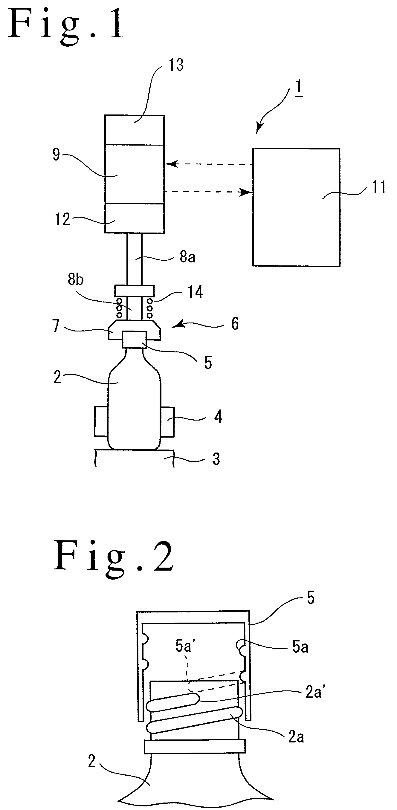
[0034] Referring to the drawings, several embodiments of the invention will now be described. A capping apparatus 1 includes a revolving body, not shown, which is rotatable in a horizontal plane. A plurality of receptacles 3 are disposed at an equal angular interval along the outer periphery of the revolving body, each receiving a vessel 2 thereon. A gripper 4 is associated with each receptacle 3 and is disposed on the revolving body to grip the barrel of the vessel 2. A capping head 6 is located above each receptacle 3 for holding a cap 5 for threadable engagement with the mouth of the vessel 2.
[0035] As shown in FIG. 2, on its outer peripheral surface, the mouth of the vessel 2 is formed with male threads 2a while the inner peripheral surface of the cap 5 is formed with female threads 5a.
[0036] The capping head 6 includes a chuck 7, which is known in itself, for detachably holding the cap 5 under pneumatic pressure, and a pair of upper and lower splined shaf...
second embodiment
[0058] Second Embodiment
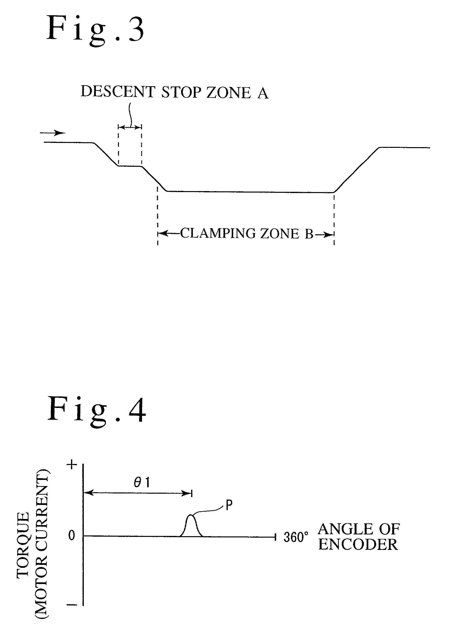
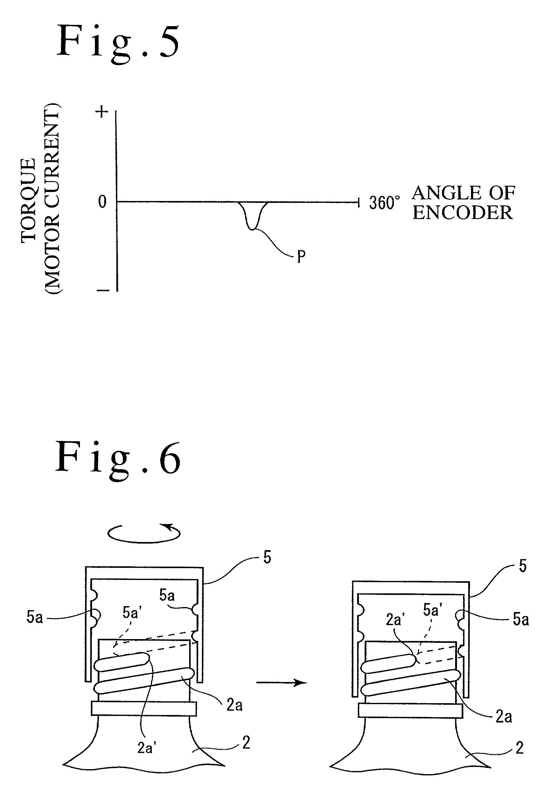
[0059] FIGS. 6 to 8 show a second embodiment of the invention. In this embodiment, there is provided a reverse zone A as shown in FIG. 7 where the controller 11 causes the motor 9 to be rotated through one revolution in a direction opposite from the clamping direction in a region where the elevating cam causes the capping head 6 to descend. In the reverse zone A, at least the lowest extremity 5a-of the female threads 5a on a cap 5 is enabled to abut against the top end 2a-of the male threads 2a on a vessel 2 (see left part of FIG. 6). In other words, the motor 9 is controlled so that in the course of descent of the capping head 6, the cap 5 is caused to rotate through one revolution in the reverse direction at the time when the lowest extremity 5a-of the female threads 5a on the cap 5 is located below the uppermost portion of the top end 2a-of the male threads 2a on the vessel 2.
[0060] When the cap 5 is rotated through one revolution in the reverse direction,...
third embodiment
[0066] Third Embodiment
[0067] FIGS. 9 to 11 illustrates a third embodiment of the invention. In the third embodiment, there is provided a rapid rotation zone A where the cap 5 is rapidly rotated in the clamping direction, the rapid rotation zone A being provided in the course of descent of the capping head 6 which takes place under the influence of the elevating cam and before the capping head 6 descends to the clamping zone B. In the rapid rotation zone A, the controller 11 drives the motor 9 to cause the cap 5 to rotate in the clamping direction from a point in time when at least the lowest extremity 5a-of the female threads 5a on the cap 5 does not abut against the top end 2a-of the male threads 2a on the vessel 2.
[0068] At this time, a rotational speed of the motor 9 is chosen to be such that the cap rotates at least through one revolution during the time the cap 5 descends in the vertical direction by an amount corresponding to the width of a single one of the male threads 2a o...
PUM
 Abstract
Description
Claims
Application Information
 - R&D
- Intellectual Property
- Life Sciences
- Materials
- Tech Scout
- Unparalleled Data Quality
- Higher Quality Content
- 60% Fewer Hallucinations
Browse by: Latest US Patents, China's latest patents, Technical Efficacy Thesaurus, Application Domain, Technology Topic, Popular Technical Reports.
© 2025 PatSnap. All rights reserved.Legal|Privacy policy|Modern Slavery Act Transparency Statement|Sitemap|About US| Contact US: help@patsnap.com


