
Offset hydraulic runner apparatus

a runner and hydraulic technology, applied in the field of runner equipment, can solve the problems of reducing the overall efficiency of operations, reducing the height of the runner equipment, and consuming prior art methods, and achieve the effect of greater capabilities

Inactive Publication Date: 2001-08-30
COLLINS BOBBY W +3
View PDF0 Cites 12 Cited by
  • Summary
  • Abstract
  • Description
  • Claims
  • Application Information

AI Technical Summary

Benefits of technology

[0007] The present invention provides several advantages. First, because the motor is horizontally offset from the drive gear, adapter, or other socket member operatively engaging a threaded member, the profile height of the runner apparatus-torque wrench assembly has been reduced to fit within the allowed the vertical dimension of confined space. The use of the horizontally offset positioned motor allows the torque wrench and runner apparatus to be used together without removing either the runner apparatus or torque wrench from engagement with the threaded member. The gear and / or pulley configuration of the present invention also allows operators to vary the speed and torque delivered by the runner apparatus, providing a runner apparatus with greater capabilities.
[0009] It is a further object of this invention to provide a runner apparatus assembly that can work in an offset manner while providing increased speed or torque.
[0010] It is a further object of this invention to provide a runner apparatus that may be used effectively and efficiently by itself or in conjunction with existing torque wrenches to increase the speed or torque applied to the nut or bolt.
[0011] It is a further object of this invention to minimize operator fatigue and the maintenance costs associated with the make-up or break-out of sections of tubular members.

Problems solved by technology

Unfortunately, the total height needed to fit both a torque wrench and a runner apparatus, which includes a motor, is often greater than six inches.
The prior art methods are time consuming and decrease the overall efficiency of operations.
The prior art devices and methods are expensive to maintain and create operator fatigue.

Method used


Image

  • Offset hydraulic runner apparatus
  • Offset hydraulic runner apparatus
  • Offset hydraulic runner apparatus

Examples


Embodiment Construction

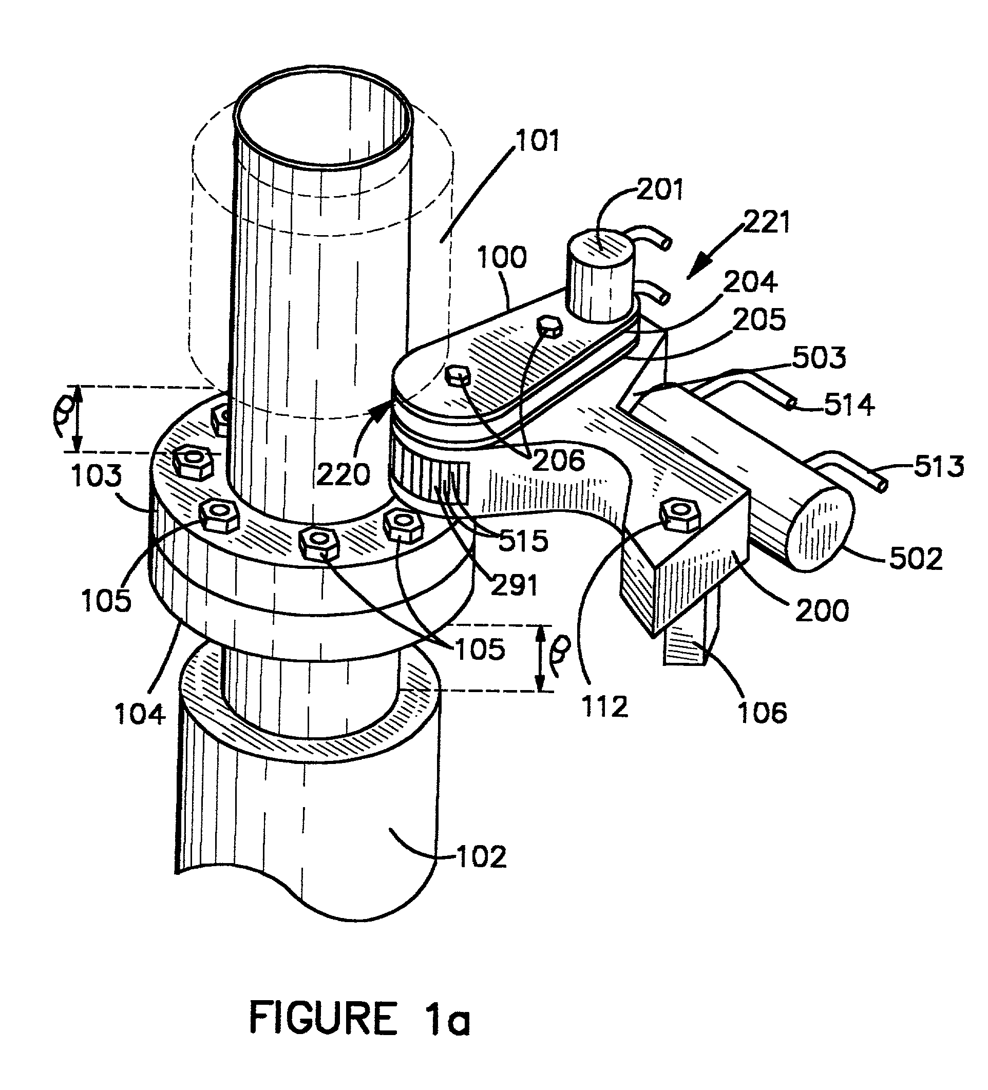
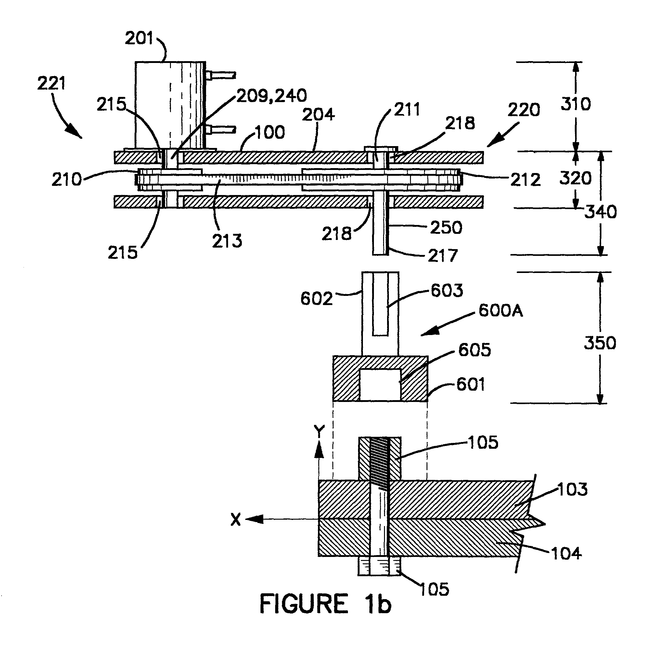
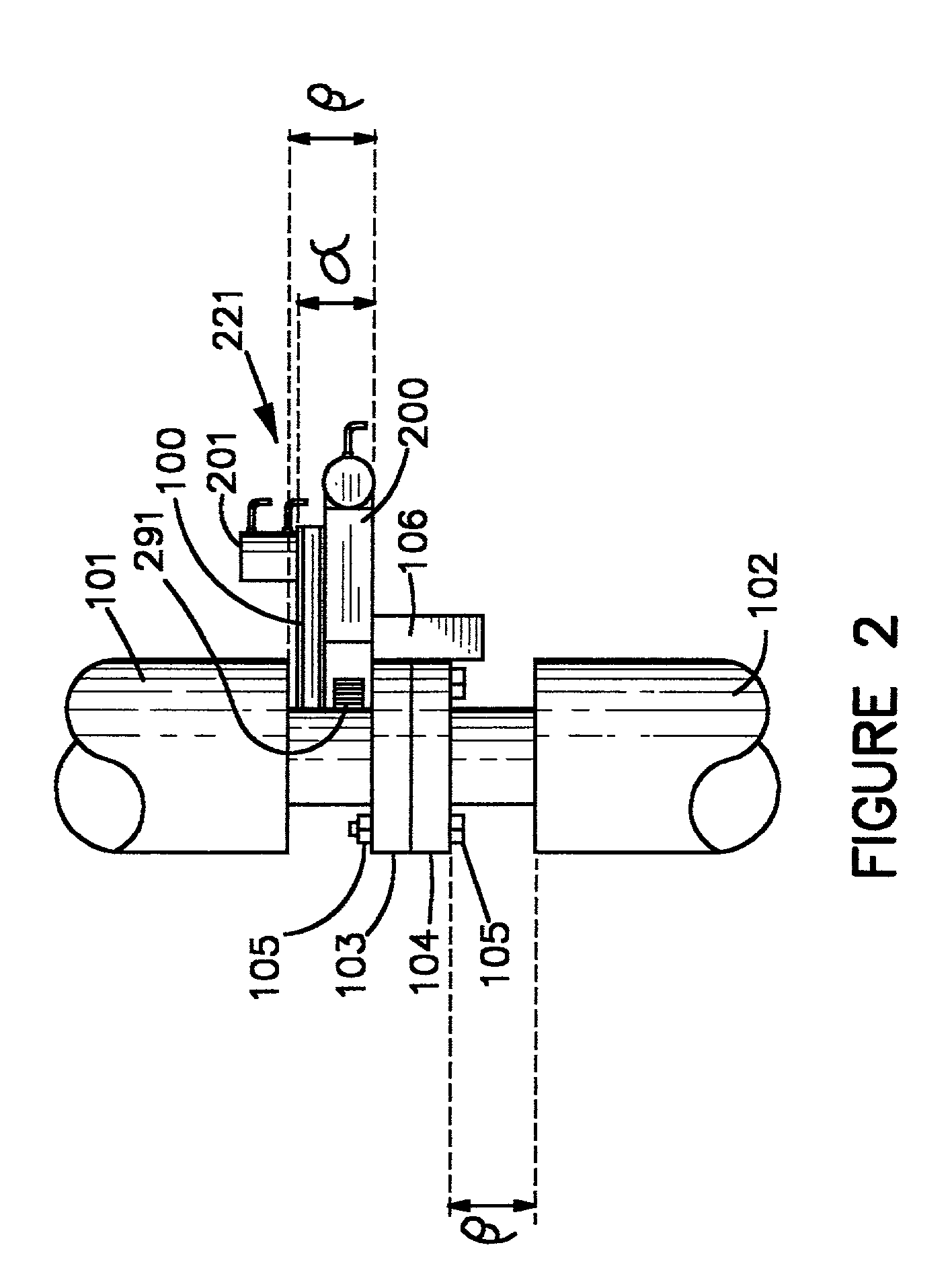
[0029] As shown in FIGS. 1a, 1b, and 2, runner apparatus 100 may be used alone (FIG. 1b) or in conjunction with a suitable torque wrench 200 (FIG. 1a, 2) to tighten or loosen threaded members 105, such as nuts and bolts, positioned in confined spaces. Threaded members 105 connect the flanges 103, 104 of tubular member 101, 102. The vertical dimension of the confined space is typically that dimension shown as confined space .beta. shown in FIGS. 1 and 2, and is usually about six inches in many applications.

[0030] Thus, it is desirable that the motor 201 on hydraulic runner apparatus 100 be positioned horizontally offset from the driving end 220 and / or positioned horizontally offset from drive head 291. Motor 201 may be positioned at first end 221. This allows torque wrench 200 and runner apparatus 100 (together referred to a "wrench assembly") to operatively engage and rotate a threaded member 105 within the vertical dimension of confined space .beta..

[0031] As used in the claims, "o...


PUM


Abstract

A runner apparatus is disclosed herein that is used alone or in combination with or incorporated into an existing torque wrench. The runner apparatus has a motor positioned offset from end operatively engaging a threaded member so that the runner apparatus or runner apparatus-torque wrench combination has a profile height that allows it to be positioned in confined spaces that are relatively small.

Description

CONTINUATION-IN-PART[0001] This is a continuation-in-part of U.S. patent application Ser. No. 09 / 302,836 which is hereby incorporated by reference in its entirety.[0002] 1. Field of the Invention[0003] This invention relates generally to a runner apparatus for threaded members, such as nuts and bolts, and more particularly to an apparatus which can operate in an offset manner allowing nuts and bolts to be turned with increased speed and torque in areas where there is decreased clearance within which to fit a runner apparatus and a torque wrench.[0004] 2. Prior Art[0005] In applications where numerous sections of tubular members having flanged ends, such as pipes, are connected ("made-up") or disconnected ("break out"), the vertical dimension of confined space within which a torque wrench and a runner apparatus must work to tighten and loosen the nuts and bolts connecting the pipes is often less than six inches. Unfortunately, the total height needed to fit both a torque wrench and a...

Claims


Application Information

Patent Timeline
Patent Type & Authority Applications(United States)
IPC IPC(8): B25B21/00
CPCB25B21/00B25B21/002B25B21/005
Inventor COLLINS, BOBBY W.DECKER, ROBERTCLOVER, DONSHIREY, MICHAEL
Owner COLLINS BOBBY W
Learn More