Oral cavity washer with video scope
a technology of video scope and oral cavity, which is applied in the field of video scope, can solve the problems of difficult to actually confirm on an image, and in ordinary households it is difficult to newly secure space to install a display
- Summary
- Abstract
- Description
- Claims
- Application Information
AI Technical Summary
Benefits of technology
Problems solved by technology
Method used
Image
Examples
first embodiment
[0037] (First Embodiment)
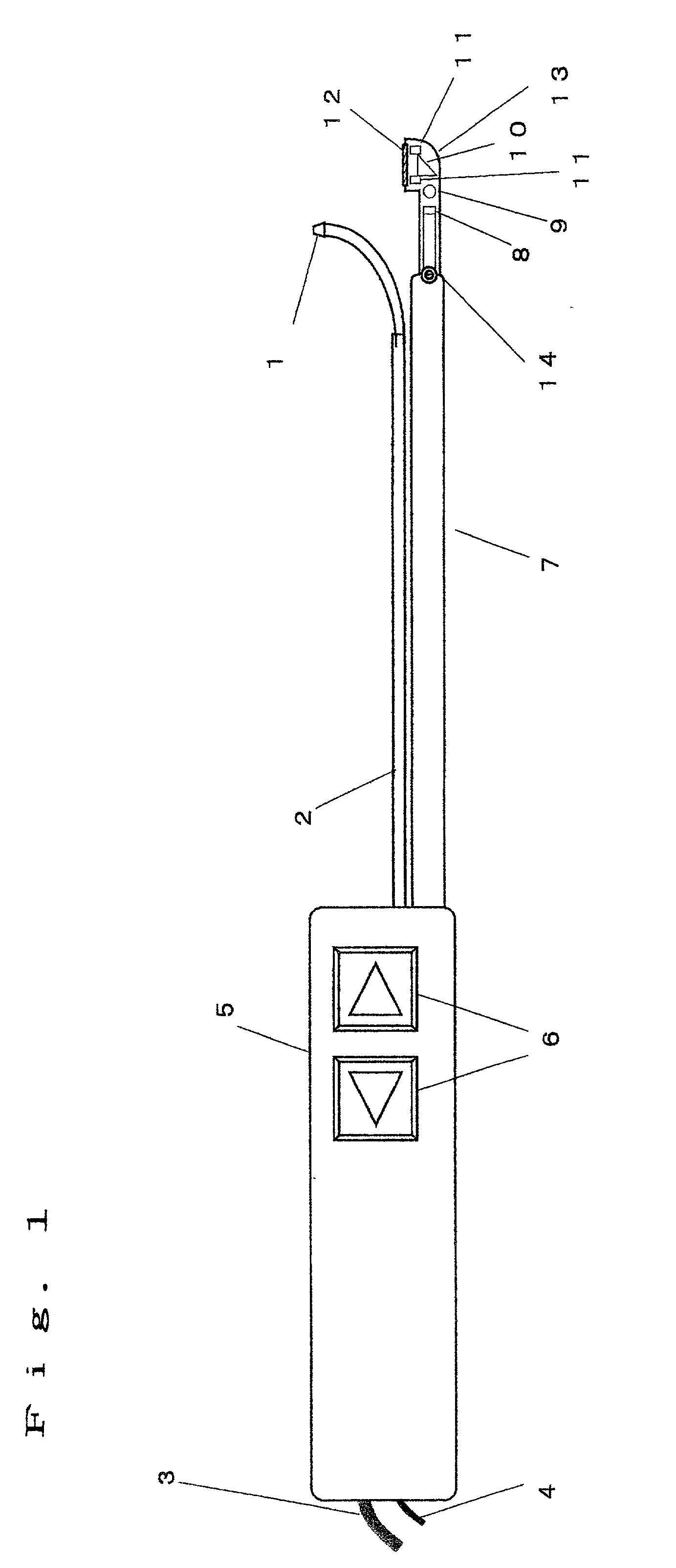
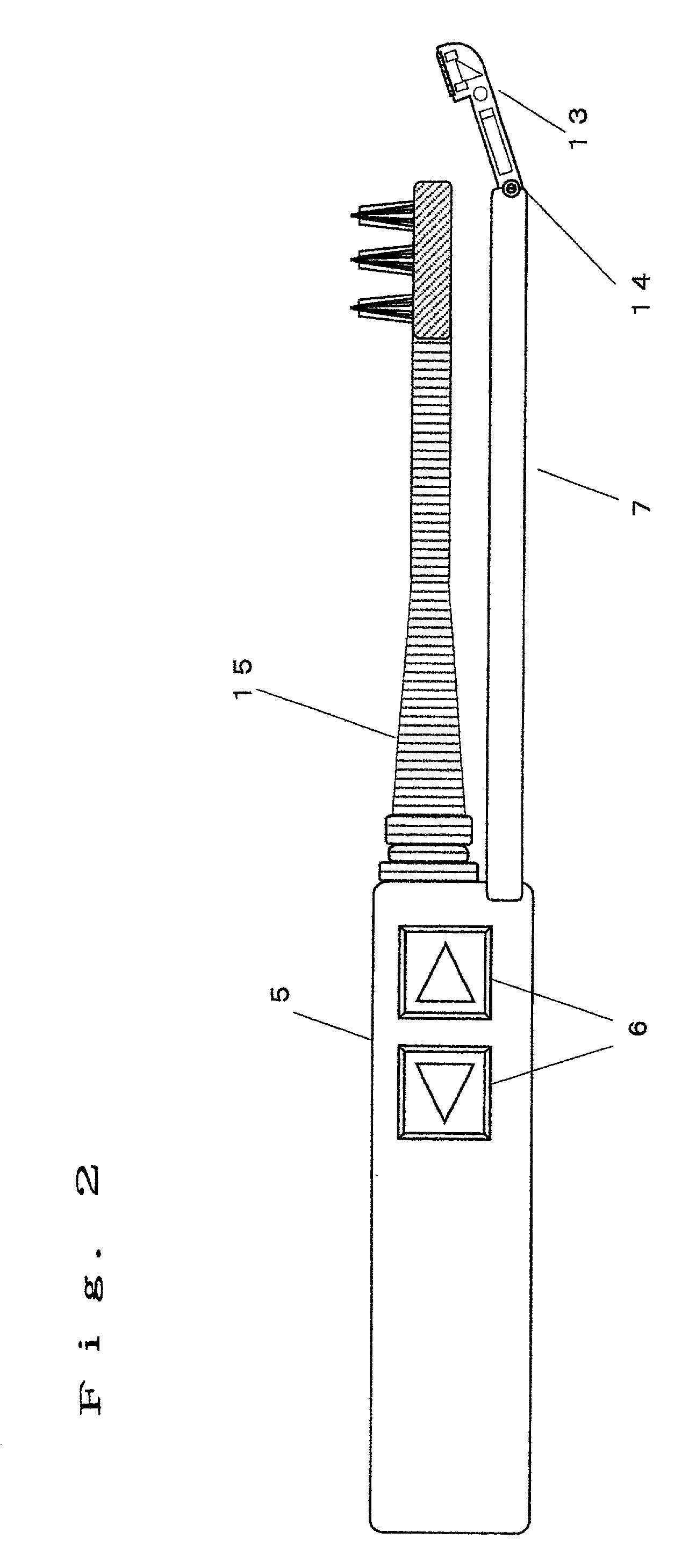
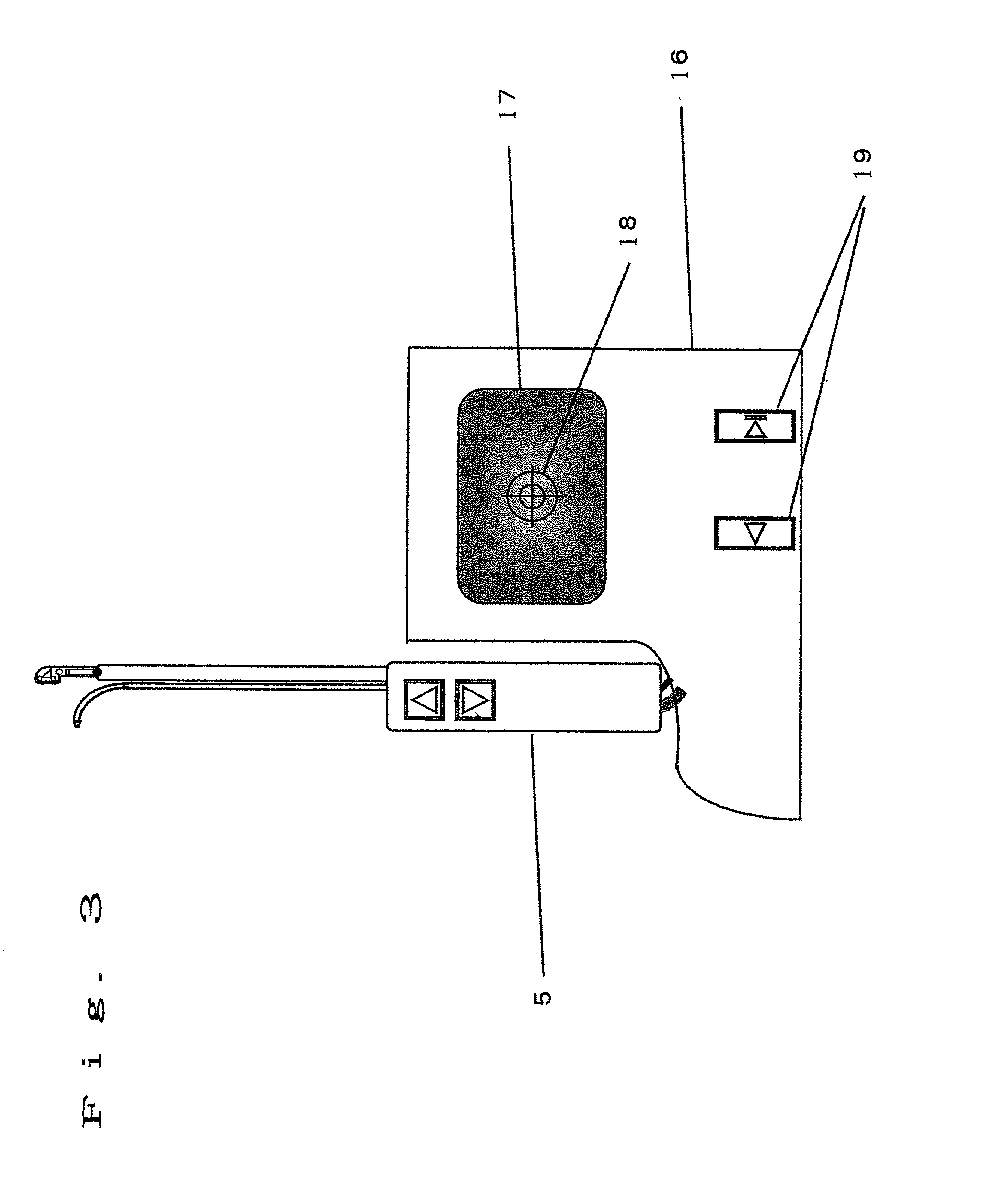
[0038] Hereinafter, with reference to FIGS. 1 to 3, the description will be made of an embodiment of the present invention.
[0039] In the present embodiment, the nozzle for jetting liquid to an object can be replaced with a toothbrush. These are replaced as required, whereby it becomes possible not only to perform washing for jetting liquid, but also to clean teeth by a toothbrush. By having this replacement function, the video scope can be utilized not only on jetting liquid, but also on cleaning teeth, which is effective.
[0040] FIG. 1 is a side view showing a portion of an oral cavity washer with a video scope according to the present embodiment. In FIG. 1, reference numeral 1 denotes a nozzle for jetting liquid, and reference numeral 2 denotes a pipe for supplying liquid to be jetted to the nozzle 1 and fixing the nozzle 1 to a grip portion 5. Reference numeral 3 denotes a tube for supplying liquid to the nozzle 1 from the main body 16 shown in FIG. 3 thro...
second embodiment
[0052] (Second Embodiment)
[0053] FIG. 4 is a side view showing a portion of an oral cavity washer with a video scope according to a second embodiment of the present invention except for the display (display 17). In FIG. 4, reference numerals 1 to 14 denote the same objects as those denoted by reference numerals 1 to 14 of FIG. 1, and have the same functions. Reference numeral 20 denotes a nozzle, which jets liquid such as water to the optical window 12. This liquid is sent from the main body 16 to the grip portion 5 through the tube 3, and is sent from the grip portion 5 to the nozzle 20 through the pipe housed in the video scope base 7. Jetting of liquid for washing this optical window 12 is controlled by a switch 6 provided at the grip portion 5 as described below.
[0054] During the washing operation for the object using liquid from the nozzle 1, bubbles or water droplets are prone to occur, and these bubbles or water droplets may adhere to the optical window 12 to hinder the image...
third embodiment
[0057] (Third Embodiment)
[0058] With reference to FIG. 4, the description will be made of a third embodiment according to the present invention.
[0059] In the second embodiment, when bubbles or water droplets adhere to the optical window 12 to hinder the image pick-up during the washing operation, the switch 6 has been operated to jet the liquid to the optical window 12 from the nozzle 20 for removing the adhered bubbles or water droplets. At this time, when the jetting velocity of the liquid from the nozzle 1 to the washing object is high among others, bubbles or water droplets may adhere to the optical window 12 in a moment by rebounding even after removal due to jetting of the liquid from the nozzle 20 to hinder the image pick-up.
[0060] In order to cope with such a case, according to the present embodiment, the nozzle 1 and the nozzle 20 automatically jet the liquid alternately. The liquid sent by a pump installed in the main body 16 is controlled by a change-over valve installed ...
PUM
 Abstract
Description
Claims
Application Information
 - R&D
- Intellectual Property
- Life Sciences
- Materials
- Tech Scout
- Unparalleled Data Quality
- Higher Quality Content
- 60% Fewer Hallucinations
Browse by: Latest US Patents, China's latest patents, Technical Efficacy Thesaurus, Application Domain, Technology Topic, Popular Technical Reports.
© 2025 PatSnap. All rights reserved.Legal|Privacy policy|Modern Slavery Act Transparency Statement|Sitemap|About US| Contact US: help@patsnap.com


