Valve for bladder control device

a valve and bladder technology, applied in the field of valves for bladder control devices, can solve the problems of compromising the performance of the device, buckling, and the device diameter

Inactive Publication Date: 2001-06-28
FEELSURE HEALTH CORP
View PDF0 Cites 0 Cited by
  • Summary
  • Abstract
  • Description
  • Claims
  • Application Information

AI Technical Summary

Benefits of technology

0007] The lumen through the housing can include a portion disposed distally of the valve seat having a diameter approximately equal to the diameter of the distal portion of the stopper. The stopper is preferably slidably disposed within this portion of the lumen for movement between the first and second positions. A second portion of the lumen, disposed distally of the first portion of the lumen, has a diameter greater than the diameter of the first portion of the lu

Problems solved by technology

Consequently, patients and their physicians desire that the diameter of the device be limited without compromising the performance of the device.
It can be appreciated that larger diameter bladder control devices could cause some discomfort du

Method used


Image

  • Valve for bladder control device
  • Valve for bladder control device
  • Valve for bladder control device

Examples


Embodiment Construction

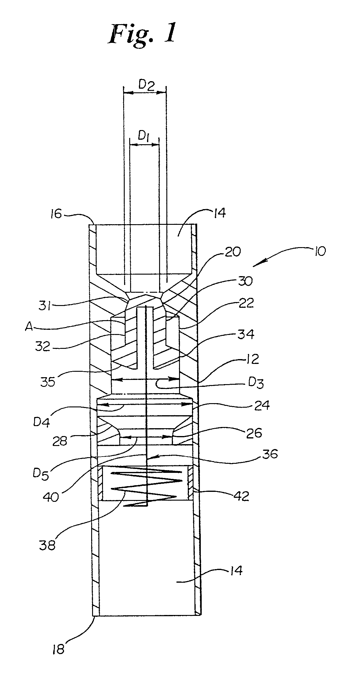
[0012] Referring now to the drawings wherein like reference numerals refer to like elements throughout the several views, FIG. 1 is a schematic cross sectional view of a valve 10 for a bladder control device in accordance with the present invention. Housing 12 can be formed from a biocompatible polymer, metal or other material. Housing 12 can be formed from a single piece or from an assembly of several pieces.

[0013] Valve 10 includes an elongate housing 12 having a lumen 14 extending therethrough from a proximal end 16 to a distal end 18. Valve 10 can be placed in the urethra of a patient. It can be retained within the urethra by proximal and distal retainers such as those disclosed in U.S. Pat. No. 5,701,916 to Kulisz et al. which is incorporated herein by reference. It should be understood, however, that the use of this valve is not limited to a configuration including the proximal and distal retainers of the referenced U.S. patent. It is contemplated that the valve could be used ...


PUM


Abstract

A valve for a bladder control device including an elongate housing having a valve seat disposed therein. A stopper is also disposed within the housing and is moveable between a first position in which the stopper engages the valve seat and a second position wherein the stopper is moved distally of the valve seat. A tension spring can be connected to the stopper to biases the stopper toward the valve seat. A lumen is defined through the housing having a first portion disposed distally of the valve seat having a diameter approximately equal to a diameter of the stopper. A second portion of the lumen disposed distally of the first portion has a greater diameter than the first portion of the lumen. Yet a third portion of the lumen disposed distally of the second portion has a diameter less than that of the first portion.

Description

BACKGROUND OF THE INVENTION[0001] The present invention relates generally to the field of bladder control devices. More particularly, the invention relates to the field of bladder control devices in which a valve is provided to control flow from the bladder of a patient.[0002] Bladder control devices related to the field of this invention include devices such as those disclosed by Kulisz et al., in U.S. Pat. No. 5,512,032 and U.S. Pat. No. 5,701,916. The former patent discloses a bladder control device including a valve which remains open under the influence of flow through the device in accordance with Bernoulli's Principle. The latter patent discloses proximally and distally disposed retainers for retaining the bladder control device within a patient's urethra. These pioneering devices can be activated in an intuitive way by a patient, simply by the patient increasing bladder pressure. The valve remains open at a lower pressure so long as a certain minimal flow rate through the va...

Claims


Application Information

Patent Timeline
IPC IPC(8): A61F2/00
CPCA61F2/0022
Inventor MIGACHYOV, VALERY
Owner FEELSURE HEALTH CORP
Why Eureka
Try Eureka