Pole frame structure of foldable tent

a tent and pole frame technology, applied in tents/canopies, constructions, building types, etc., can solve the problems of direct damage, rubbed tent cloth will be damaged, and the support rod assembly cannot provide a firm support, so as to prevent the top of the tent from sagging, enhance the support of the tent, and be stable in use.

Active Publication Date: 2022-11-15
CAMPVALLEY XIAMEN LEISURE PRODS
View PDF13 Cites 4 Cited by
  • Summary
  • Abstract
  • Description
  • Claims
  • Application Information

AI Technical Summary

Benefits of technology

[0008]In view of the defects of the prior art, the primary object of the present invention is to provide an improved pole frame structure of a foldable tent, which can enhance the supporting force of the top of the tent, so that the support rods on the top of the tent can be supported more stably in use to prevent the tent cloth from being damaged by oblique support rods.
[0018]When the tent is unfolded for use, one end of the oblique support rod, facing the top support rod assembly, is blocked by the stopper. The oblique support rod will abut against the stopper to prevent the end of the oblique support rod pivoted with the top support rod assembly from excessively rotating about the pivot axis to cause the top support rod assembly to sag. As a result, the support height of the oblique support rod to the top support rod assembly is also increased, so that the top of the tent is fully extended, and the tent cloth on the top of the tent is further supported and expanded. The tent cloth is less likely to cause problems such as sag or accumulation of water.
[0020]Furthermore, one end of the top module, facing the top support rod assembly, is provided with a limiting component. The upper end face of the top support rod assembly abuts against the lower end face of the limiting component after the pole frame structure of the tent is unfolded. The limiting component is configured to restrict the rotation of the connecting rod, so that the end of each top support rod assembly close to the center of the tent cannot be deformed downward, thereby enhancing the support of the top of the tent. This makes the support rods on the top of the tent more stable in use, and can prevent the top of the tent from sagging. Further, when the tent cloth is supported and expanded, the tent cloth is less likely to cause problems such as sag or accumulation of water. This increases the beauty of the tent and improves the service life of the tent.

Problems solved by technology

In a windy situation, the tent cloth may sway up and down.
The oblique support rod pivotally connected to the top support rod assembly cannot provide a firm support.
After long-term use, the rubbed part of the tent cloth will be damaged due to aging, or it will be directly damaged by the oblique support rod.
In addition, when in use, it was found that the support effect of the connecting member on the connecting rod close to one side of the pivot seat is only effective at its end.
Therefore, the connecting member not only increases the production cost of the tent but also makes the assembly of the tent cumbersome and time-consuming.
In addition, the connection between the pivot seat at the center of the tent and the top support rod assemblies is still unstable.
The pivot seat may drive each top support rod assembly to sway up and down in the center of the tent frame, which will easily cause the top support rod assemblies to sag in the center of the tent.
As a result, the tent cloth secured on the top of the tent frame sags, affecting the normal use of the tent.
Especially when it is rainy, rainwater will inevitably accumulate in the sag area of the tent cloth and cannot be discharged to the surroundings, which will seriously affect the normal use of the tent and even cause the tent to collapse.
For such a tent with a supporting structure on its top, the top support rod assemblies do not have sufficient support when in use.

Method used


Image

  • Pole frame structure of foldable tent
  • Pole frame structure of foldable tent
  • Pole frame structure of foldable tent

Examples


Embodiment Construction

[0029]Embodiments of the present invention will now be described, by way of example only, with reference to the accompanying drawings.

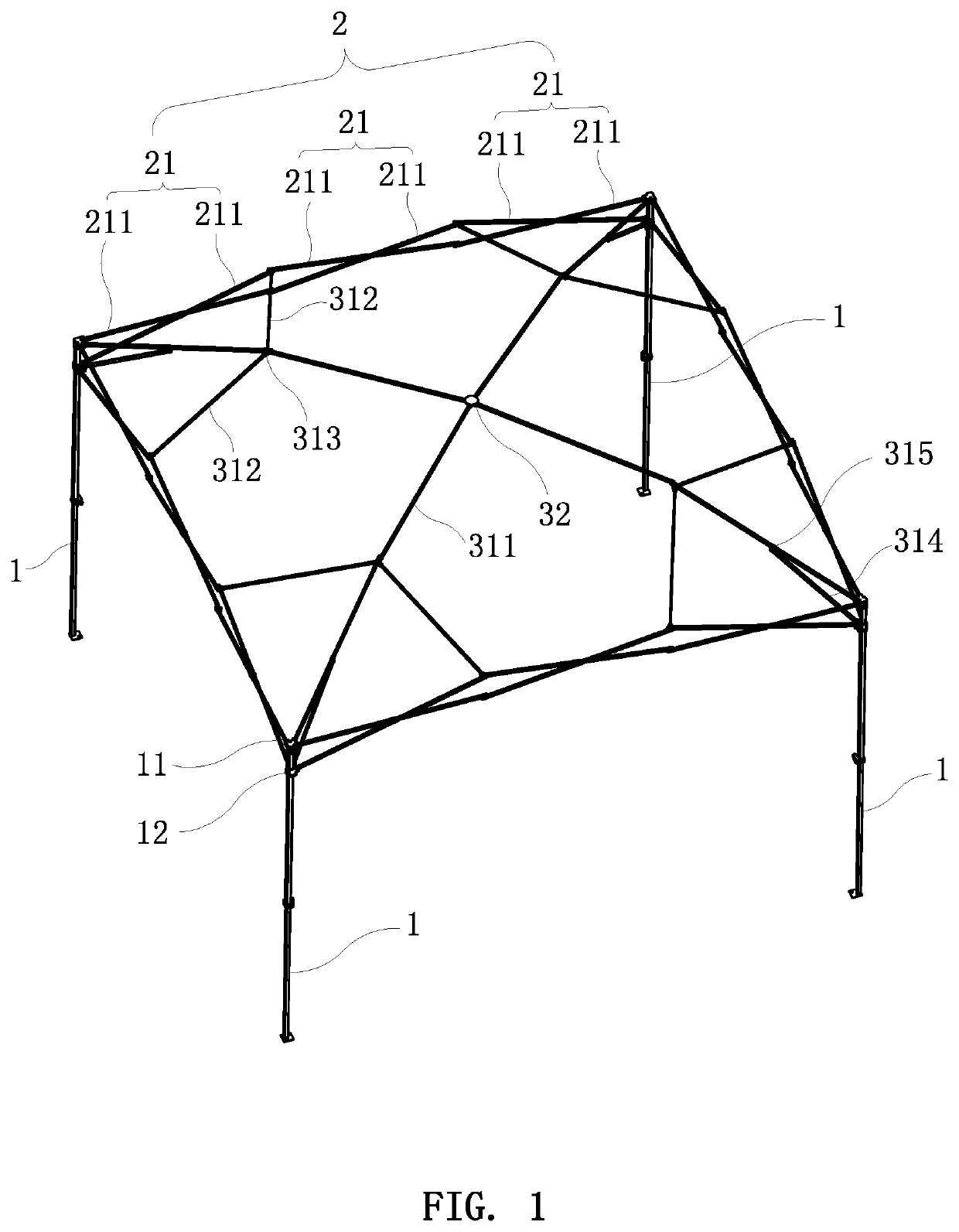
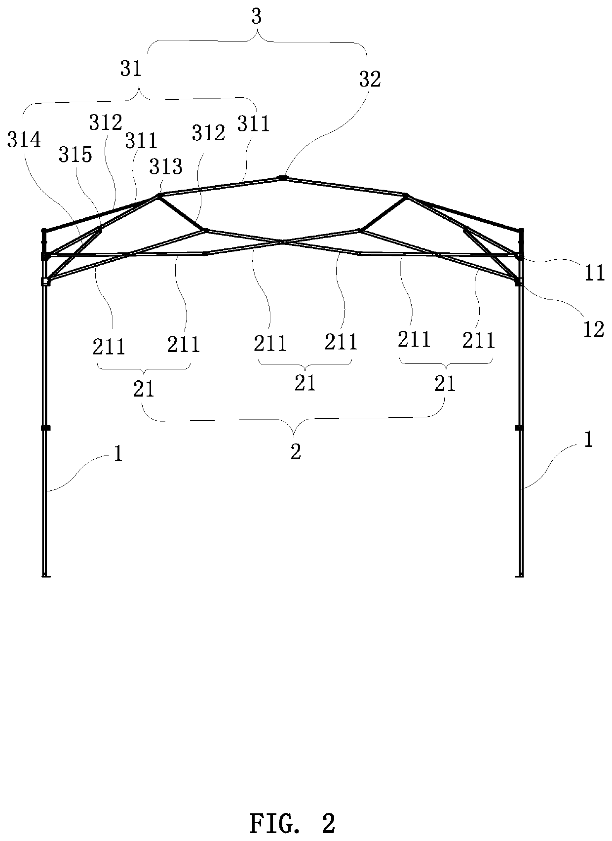
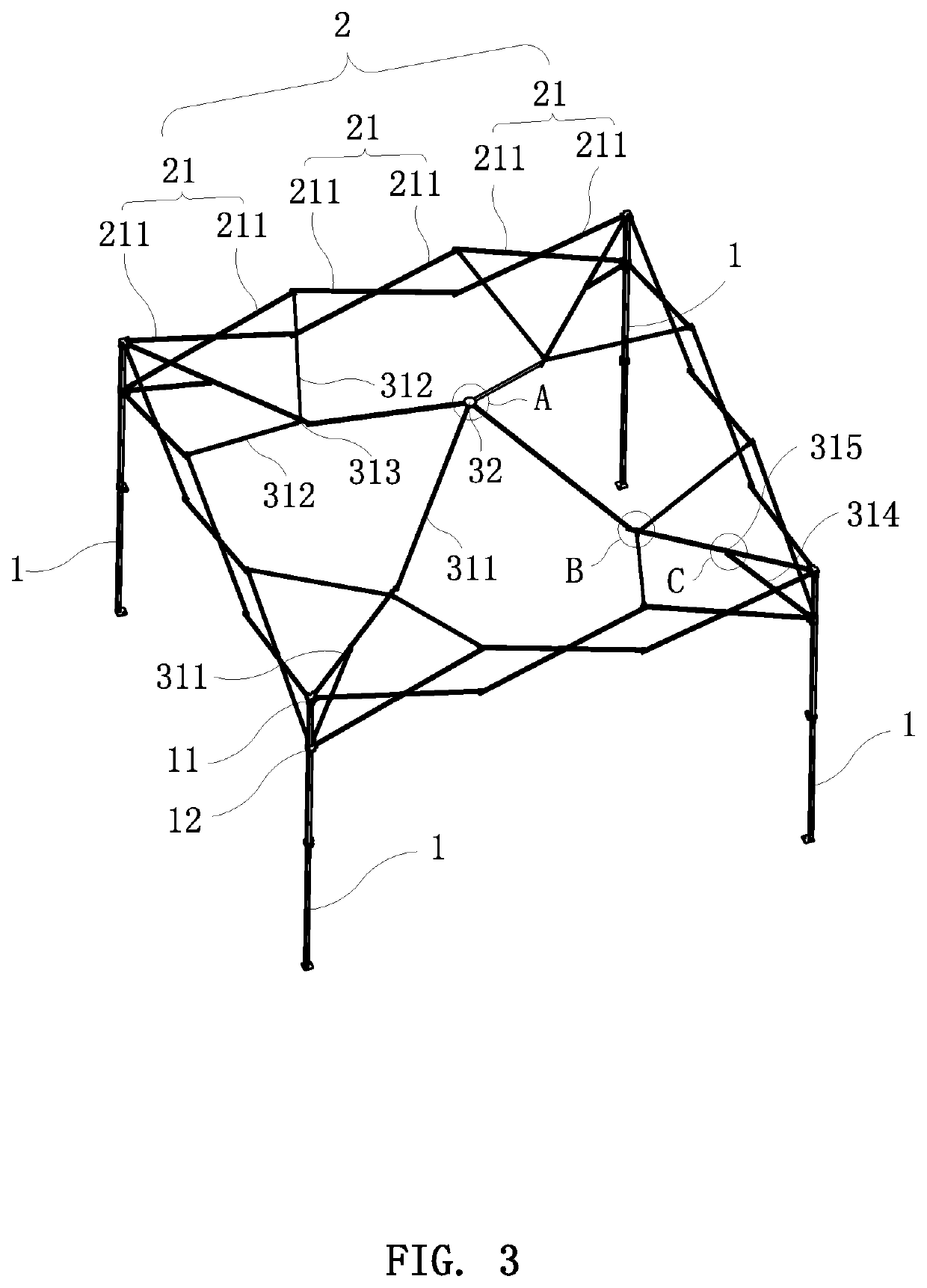
[0030]Referring to FIG. 1 through FIG. 8, the present invention discloses an improved pole frame structure of a foldable tent. The pole frame structure of the present invention comprises at least three upright poles 1. In this embodiment, the pole frame structure comprises four upright poles 1, which may be composed of six or eight upright poles 1. In order to facilitate the folding and use of the tent, the upright pole 1 may be a telescopic pole. A side support rod unit 2 is pivotally connected between every adjacent two of the upright poles 1 to support the sides of the tent. Each side support rod unit 2 includes at least two side cross support rod assemblies 21. In this embodiment, each side support rod unit 2 includes three side cross support rod assemblies 21. Each side cross support rod assembly 21 includes two crossed side support rods 211 that...


PUM


Abstract

An improved pole frame structure of a foldable tent includes upright poles, side cross support rod assemblies, and a top support rod unit. The top support rod unit includes a top module provided with a limiting component, top support rod assemblies, and oblique support rods. One end of each oblique support rod is connected to the respective top support rod assembly by means of a slider provided with a stopper, and the other end of the oblique support rod is pivotally connected to the respective side cross support rod assembly. The structure enhances, by means of the stopper and the limiting component, the stability of the oblique support rods supporting tent cloth, and prevents the tent cloth from being damaged by the oblique support rods.

Description

BACKGROUND OF THE INVENTION1. Field of the Invention[0001]The present invention relates to a tent frame, and more particularly to an improved pole frame structure of a foldable tent.2. Description of the Prior Art[0002]A tent generally includes a piece of tent cloth and a tent frame. The tent cloth is fixedly installed on the top of the tent frame, so that a sheltered use space is formed under the support of the tent frame. Because of the practicability of the tent, it is widely used in various temporary places.[0003]Besides, in order to make the tent convenient to carry and have a large sheltered use space, the structure of the tent frame often makes the tent have the functions of folding and unfolding. A common rectangular tent frame includes four upright poles. A side cross rod unit is provided between every adjacent two of the upright poles. The top of the tent frame is provided with a top support rod unit. The top support rod unit includes four top support rod assemblies distri...

Claims


Application Information

Patent Timeline
Patent Type & Authority Patents(United States)
IPC IPC(8): E04H15/50E04H15/46
CPCE04H15/50E04H15/46E04H15/34E04H15/18
Inventor BAIK, KWANG HOCHEN, RENHUA
Owner CAMPVALLEY XIAMEN LEISURE PRODS
Why Eureka
Try Eureka