
Anomaly location identification device, anomaly location identification method, and program

Active Publication Date: 2022-11-01
NIPPON TELEGRAPH & TELEPHONE CORP
View PDF8 Cites 0 Cited by
  • Summary
  • Abstract
  • Description
  • Claims
  • Application Information

AI Technical Summary

Benefits of technology

The patent text explains how to improve the accuracy and speed of identifying abnormal locations. The technical effect of this patent is to provide a better method for identifying abnormal locations.

Problems solved by technology

However, in this method, only the presence or absence of an anomalous state in the entire system can be determined, and it is not possible to identify which observation information item of which one of the devices relates to the anomaly.

Method used


Image

  • Anomaly location identification device, anomaly location identification method, and program
  • Anomaly location identification device, anomaly location identification method, and program
  • Anomaly location identification device, anomaly location identification method, and program

Examples


Embodiment Construction

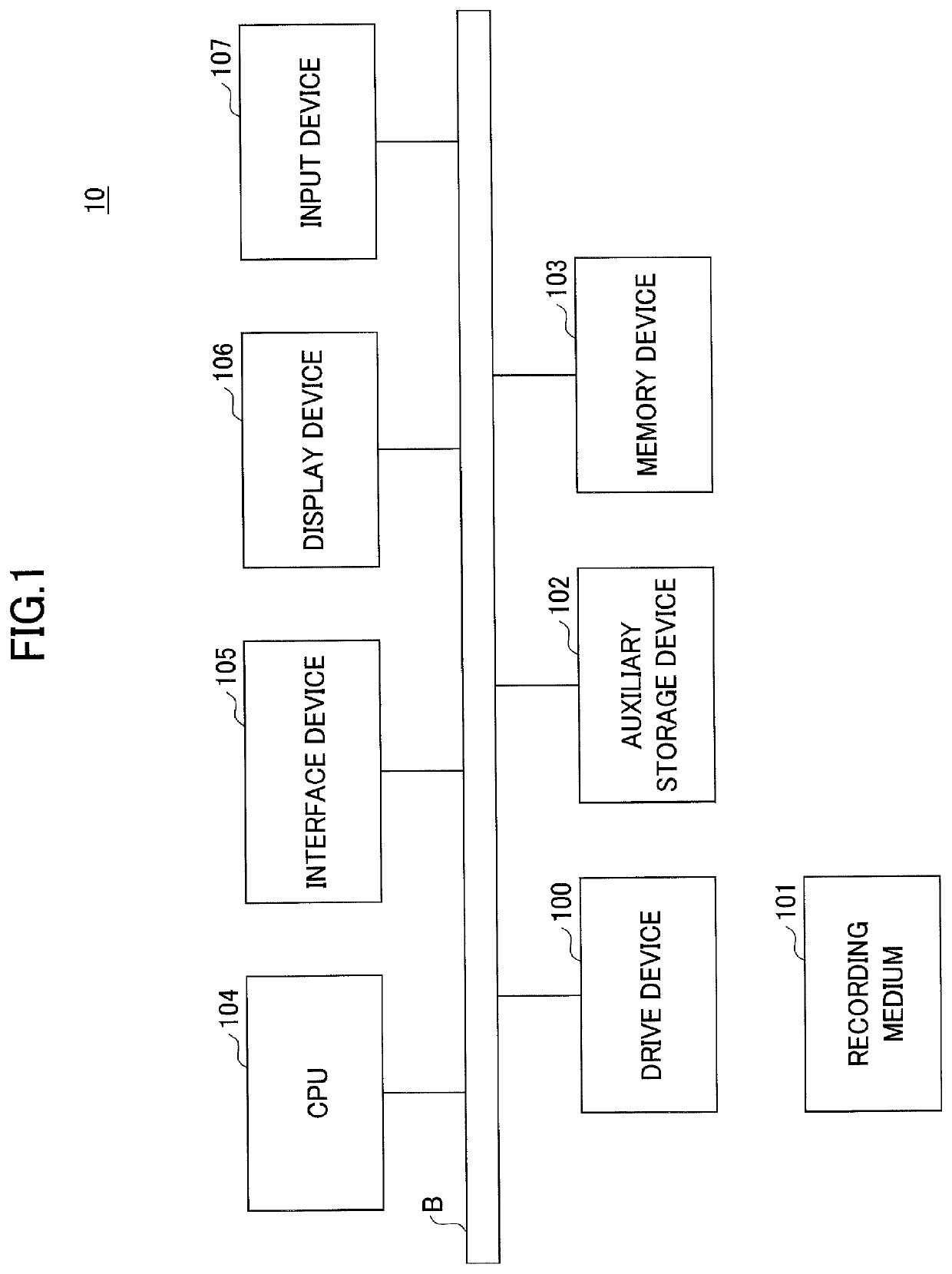
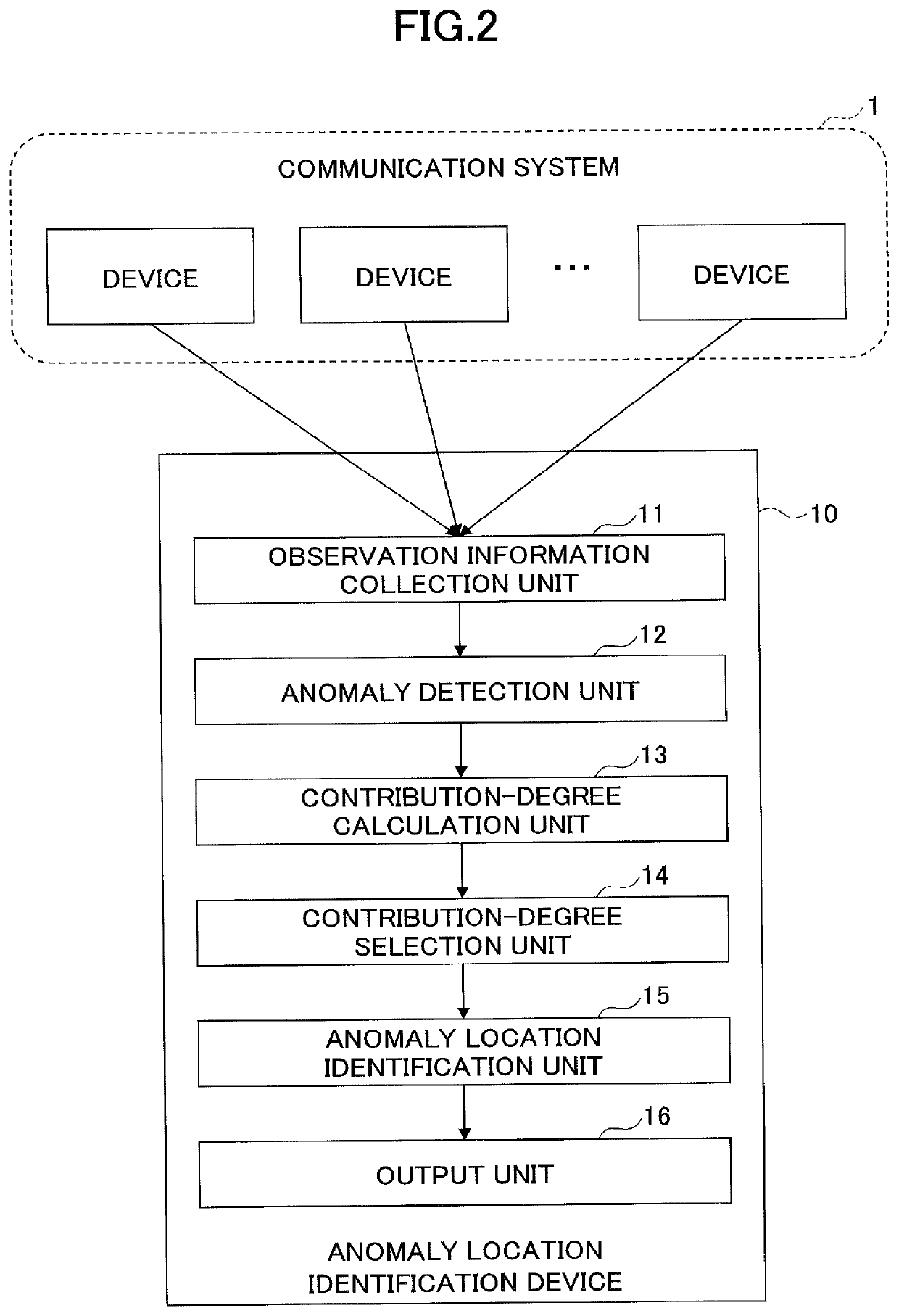
[0021]In the following, embodiments of the present invention will be described with reference to the drawings. In the present embodiment, anomaly detection techniques are effectively linked with anomaly location / cause identification techniques to improve the precision and calculation speed of anomaly location / cause identification.

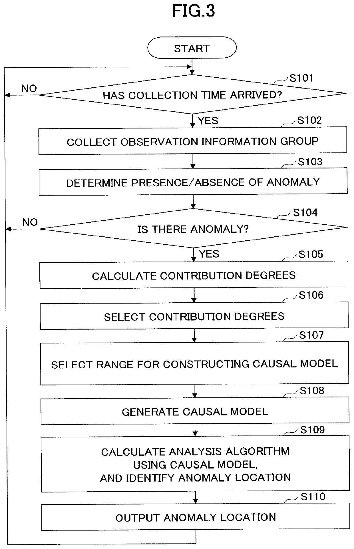
[0022]By using an information group output from devices (hereafter, referred to as the “observation information group”) in a system including multiple devices to be observed, and applying the anomaly detection techniques to determine the presence or absence of an anomaly in the entire system, the presence or absence of an anomaly in the entire system is determined. If an anomaly is present in the system, for each item of information included in the observation information group (hereafter, referred to as the “observation information”), an index indicating a degree of contribution to the detected anomaly (hereafter, referred to as the “contribution degree”) ...


PUM


Abstract

An anomaly location identification device includes a determination unit configured to determine presence or absence of an anomaly by inputting part or all of information items output from a plurality of devices into an anomaly detection algorithm; a calculation unit configured to calculate, in response to a determination made by the determination unit that an anomaly is present, with respect to one of the information items, an index indicating a degree of contribution to the anomaly; and an identification unit configured to perform calculation by an analysis algorithm using a causal model receiving the index as input, to identify an anomalous device, to improve the precision and calculation speed related to identification of an anomaly location.

Description

TECHNICAL FIELD[0001]The present invention relates to an anomaly location identification device, an anomaly location identification method, and a program.BACKGROUND ART[0002]When handling an anomaly in a communication system, it is important to rapidly execute (1) anomaly detection, and (2) anomaly location / cause identification, and for each of (1) and (2), various methods have been proposed (e.g., Non-patent documents 1 to 7).[0003]First, regarding (1), a method has been generally known that individually calculates the outlierness or the like for each device in the system, by using observation information of the device, and if the outlierness exceeds a threshold, determines it as an anomaly to raise an alert. In this method, an anomaly detection method is applied to the respective devices independently; therefore, if an anomaly is detected, it is possible to identify which observation information item of which one of the devices relates to the anomaly. Meanwhile, as in Non-patent d...

Claims


Application Information

Patent Timeline
IPC IPC(8): G06F11/00G06F16/23G06F11/07
CPCG06F16/2365G06F11/0754G06F11/07G06F16/215
Inventor MATSUO, YOICHIIKEDA, YASUHIROWATANABE, KEISHIROKAWAHARA, RYOICHI
Owner NIPPON TELEGRAPH & TELEPHONE CORP
Learn More