
Medical pressure measuring device and breathing apparatus

a technology of medical pressure and measuring device, which is applied in the direction of fluid pressure measurement, measurement device, instruments, etc., can solve the problems of measuring error, measuring error is a difference in pressure, and devices sometimes do not show

Active Publication Date: 2022-10-04
MAQUET CRITICAL CARE
View PDF12 Cites 0 Cited by
  • Summary
  • Abstract
  • Description
  • Claims
  • Application Information

AI Technical Summary

Benefits of technology

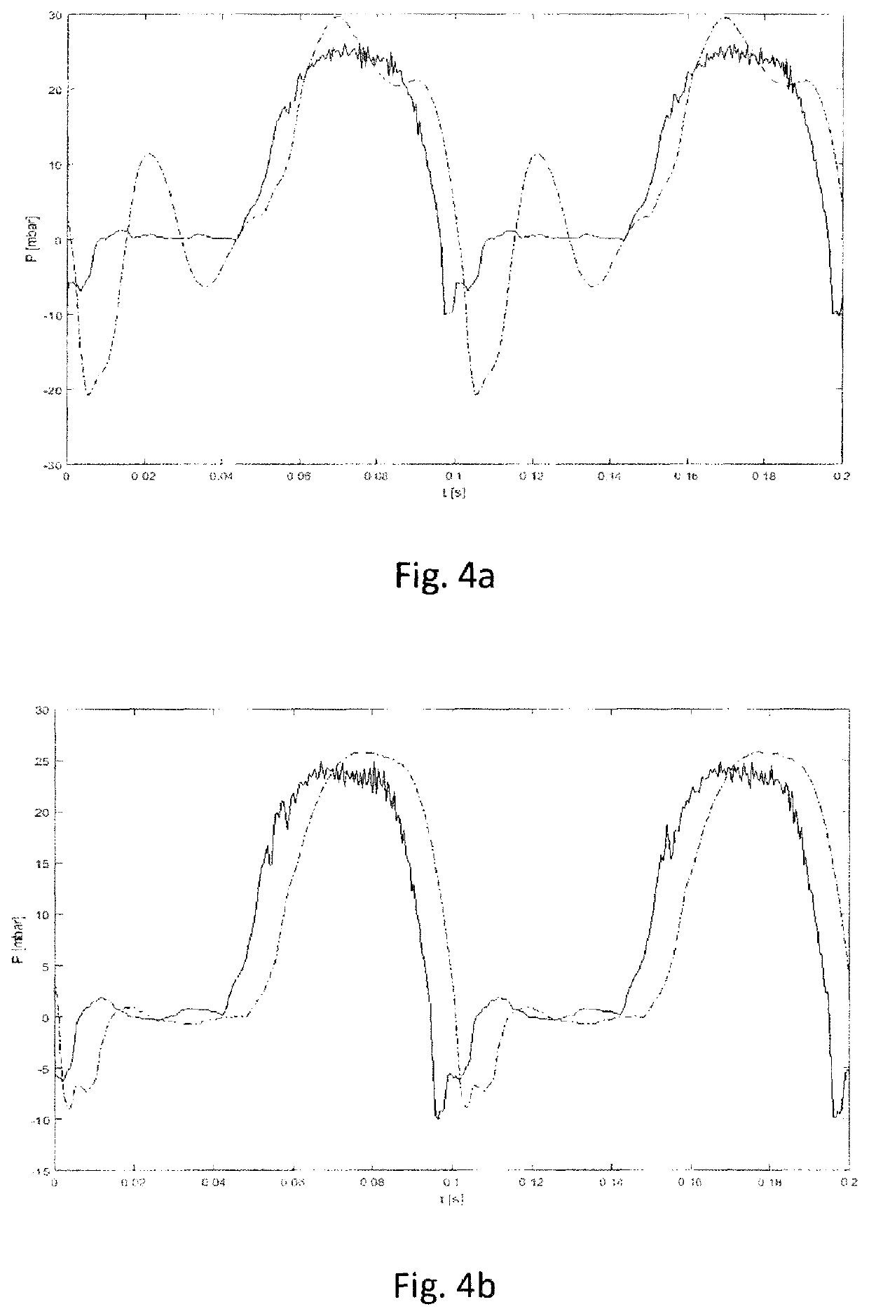
[0008]The present disclosure also relates to a medical pressure measuring device and a breathing apparatus that compensate for distorting physical effects, such as acoustic resonance, when measuring the pressure of a fluid, or at least help to reduce the effect of these distorting physical effects.
[0031]In one example of this disclosure, the breathing apparatus further comprises a purge flow arrangement arranged to continuously or intermittently purge the pressure sampling tube. This has the advantage of reducing contaminants in the sampling tube, thereby reducing the risk of potentially harming the subject.

Problems solved by technology

It has been realised that medical pressure measuring devices sometimes do not show the “right” value (i.e., the actual value) for pressure measurements although they are not malfunctioning because there may be a cause of measuring error within the design of the fluid flow system undergoing measurement.
It has turned out that this source of measuring error can be caused by a phenomenon called acoustic resonance, especially in connection to so-called high frequency oscillations, HFO.
The measuring error is a difference in pressure between the point of measurement where the sensor is located and the sampling point where the varying pressure is to be determined.

Method used


Image

  • Medical pressure measuring device and breathing apparatus
  • Medical pressure measuring device and breathing apparatus
  • Medical pressure measuring device and breathing apparatus

Examples


Embodiment Construction

[0040]FIG. 1 depicts schematically an embodiment of a medical pressure measuring device 100. In the following, the medical pressure measuring device 100 will be denoted device 100. The device 100 comprises a pressure sensor 110 and a damping arrangement 120.

[0041]The device 100 is suitable for measuring a pressure of a pressurized breathing gas supplied to a subject 160 by a breathing apparatus. Embodiments of the breathing apparatus will be described later, for example in relation to FIG. 3. The subject 160 can be a human being. The subject 160 can be an animal. Examples of breathing gases are air, oxygen, an oxygen-nitrogen mixture, a helium-oxygen mixture, so called “Heliox”, or any other gas comprising one or several of the aforementioned components. In one example the device 100 is arranged for measuring a pressure of a pressurized breathing gas supplied to the subject 160.

[0042]The pressure sensor 110 is arranged at a point of measurement 195. The pressure sensor 110 can be an...


PUM

PropertyMeasurementUnit
distanceaaaaaaaaaa
distanceaaaaaaaaaa
temperatureaaaaaaaaaa

Abstract

A medical device measures a pressure of a pressurized breathing gas and includes a pressure sensor arranged at a point of measurement and measures the pressure of a sample gas at a sampling point. The sampling point and the point of measurement are connected by a pressure sampling tube in which a pressure wave of the sample gas can propagate from the sampling point to the point of measurement. The tube has a sampling tube volume and an acoustic impedance. The device further includes a damping arrangement fluidly communicating with the tube. The damping arrangement includes a flow restrictor and a receptor chamber arrangement. The receptor arrangement includes a receptor chamber which receives the pressure wave. The restrictor correlates to the acoustic impedance to prevent acoustic resonance in the tube. The receptor chamber correlates at least to the tube volume to prevent acoustic resonance in the tube.

Description

TECHNICAL FIELD[0001]The present disclosure relates to a medical pressure measuring device and a breathing apparatus.BACKGROUND ART[0002]For medical devices it is often important to measure the pressure of a fluid. This is, for example, known from measuring blood pressure. Also gaseous fluids need sometimes to be measured, such as gaseous media (i.e., gases, mixture of gases, and mixture of gases with some liquid droplets) used in breathing apparatuses. It is in this respect important that the measured pressure of the fluid is accurate. This is due to the fact that the measured pressure is used, for example, for analysing the health state of a subject and / or for controlling properties of a fluid supplied to the subject. Delivery of fluids with the wrong properties may sometimes jeopardize the safety of the subject.[0003]For practical reasons, pressure measurements are not always possible to perform at a desired point of measurement. This can, for example, be due to the fact that a p...

Claims


Application Information

Patent Timeline
Patent Type & Authority Patents(United States)
IPC IPC(8): A61M16/08A61M16/00G01L19/06A61M16/10
CPCA61M16/0858A61M16/0006A61M16/0833A61M16/0866G01L19/0609A61M16/0096A61M2016/0027A61M2016/102
Inventor HALLBÄCK, MAGNUS
Owner MAQUET CRITICAL CARE
Learn More