
Power storage device

a storage device and power technology, applied in the direction of electrical equipment, cell components, cell component details, etc., can solve the problems of deviation between the electrode plates, difficulty in holding the secondary cells in a stable manner, etc., and achieve the effect of suppressing the reactive force generated by the expansion of the secondary cells and improving the resistance of the secondary cells to vibration

Active Publication Date: 2022-09-20
PANASONIC INTELLECTUAL PROPERTY MANAGEMENT CO LTD
View PDF14 Cites 0 Cited by
  • Summary
  • Abstract
  • Description
  • Claims
  • Application Information

AI Technical Summary

Benefits of technology

The present patent provides a power storage device that can hold secondary cells in a stable manner while still allowing them to change volume from charging and discharging. The device improves resistance against vibration when the secondary cells have low soil level, and suppresses the reactive force generated by the expansion of the cells when the soil level is high.

Problems solved by technology

When the SOC of the secondary cells is low, force binding the secondary cells becomes small due to the contraction of the secondary cells; accordingly, it is assumed that it will be difficult to hold the secondary cells in a stable manner and a deviation between the electrode plates caused by vibration will occur.

Method used


Image

  • Power storage device
  • Power storage device
  • Power storage device

Examples


Embodiment Construction

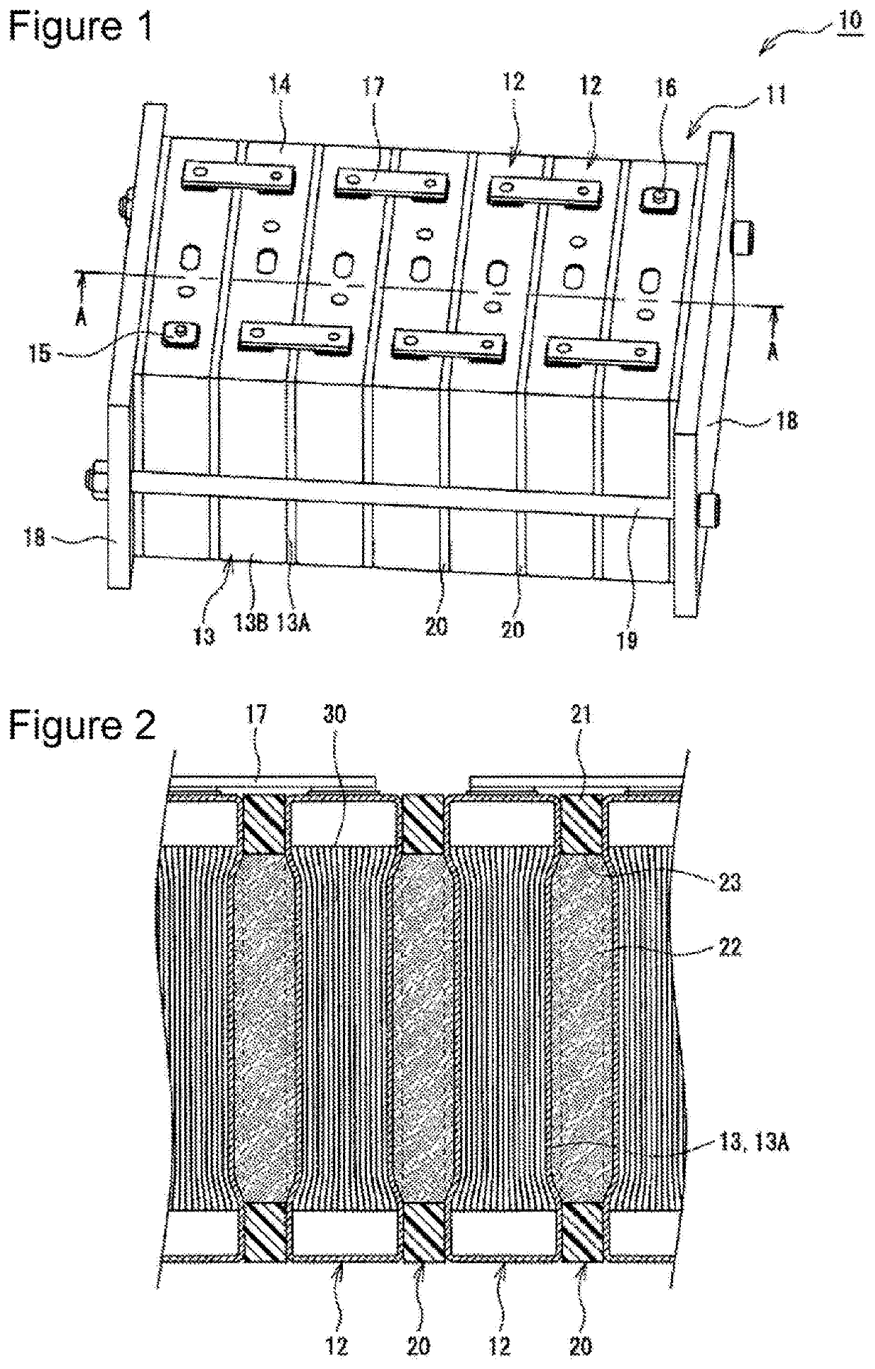
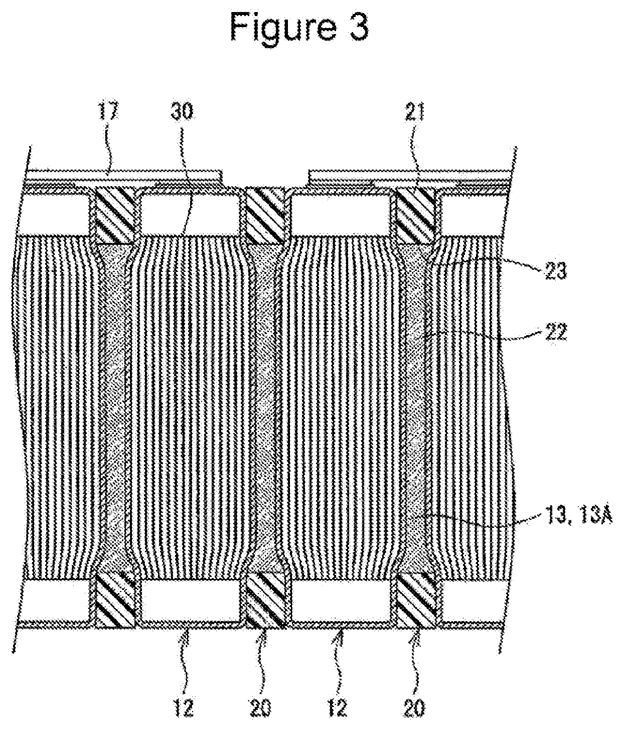
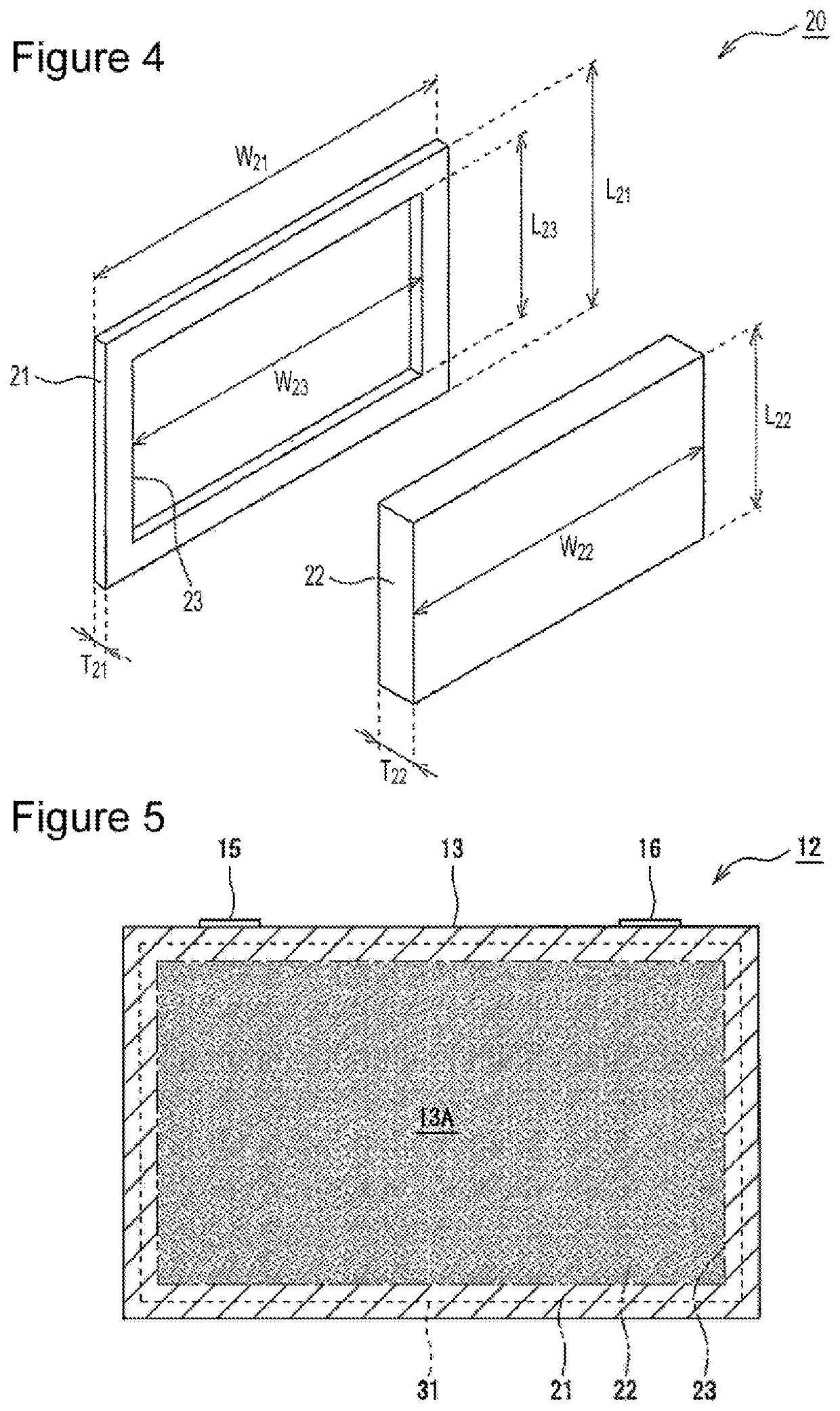
[0014]Hereinafter, referring to the drawings, examples of an embodiment will be described in detail. Note that the power storage device of the present disclosure is not limited to the embodiment described below. The drawings referred to in describing the embodiment are illustrated in a schematic manner, and the dimension ratio and the like of the components depicted in the drawings are to be determined after taking the following description into consideration. Note that in the present description, the expression “substantially” is, when described with “substantially parallel” as an example, intended to mean both a completely parallel state and a practically parallel state.

[0015]While a power storage device provided with a cell stack body including a plurality of secondary cells and a plurality of buffer plates is illustrated hereinafter as an example, the power storage device according to the present disclosure may be configured of a single secondary cell and two buffer plates that ...


PUM

PropertyMeasurementUnit
thickness T21aaaaaaaaaa
thickness T22aaaaaaaaaa
thickness T21aaaaaaaaaa

Abstract

The power storage device is provided with a cell stack body formed by alternately arranging a plurality of secondary cells and a plurality of buffer plates. Each of the buffer plates has a non-deformable section and a deformable section that is elastically deformed according to a volume change in the secondary cell. The non-deformable section has a through hole in which the deformable section is fitted. The deformable section is formed thicker than the non-deformable section.

Description

TECHNICAL FIELD[0001]The present disclosure relates to a power storage device.BACKGROUND ART[0002]Hitherto, a power storage device including secondary cells and buffer plates are known. For example, PTL 1 discloses a power storage device formed of a plurality of secondary cells electrically coupled to each other and a plurality of buffer plates alternately arranged in a predetermined direction, which are bound while a load is applied thereto in a direction of the above arrangement. Furthermore, PTL 1 discloses a configuration in which a deformable section that allows a volume change in the secondary cell caused by charging and discharging is formed in a contact surface of the buffer plate in contact with the secondary cell, and in which a non-deformable section that does not allow the volume change of the secondary cell is formed.CITATION LISTPatent Literature[0003]PTL 1: Japanese Published Unexamined Patent Application No. 2014-157747 Summary of Invention[0004]As described above, b...

Claims


Application Information

Patent Timeline
Patent Type & Authority Patents(United States)
IPC IPC(8): H01M50/293H01M50/289H01M50/291H01M50/209H01M50/242
CPCH01M50/293H01M50/289H01M50/291H01M50/264H01M50/209H01M50/242Y02E60/10
Inventor OKA, TAKUYAYOSHIZAWA, HIROSHIMATSUTA, SHIGEKIARAKI, YOSHIAKI
Owner PANASONIC INTELLECTUAL PROPERTY MANAGEMENT CO LTD
Learn More