
Wheel and airless tire assembly

a technology of airless tires and wheels, applied in the field of airless tires, can solve the problems of difficult puncture repair, less flexible airless tires, less comfortable ride, etc., and achieve the effects of minimizing shock and rattle, improving durability of outer wheels, and comfortable rid

Active Publication Date: 2022-09-13
LEE SUNG KEE
View PDF11 Cites 0 Cited by
  • Summary
  • Abstract
  • Description
  • Claims
  • Application Information

AI Technical Summary

Benefits of technology

[0009]The present invention provides an airless tire mainly used on forklifts and industrial, agricultural, mining, and construction applications, that prevents a tread part from peeling off the outer wheel as it comes into contact with the road surface during rotation or driving, gives a more comfortable ride by minimizing shocks and rattles caused by an irregular road surface, and improves the durability of the outer wheel.
[0019]As explained with respect to the above aspect, the airless tire thus constructed according to the present invention has the advantages of preventing a tread part from peeling off the outer wheel as it comes into contact with the road surface during rotation or driving, giving a more comfortable ride by minimizing shocks and rattles caused by an irregular road surface, and improving the durability of the outer wheel to ensure safety.

Problems solved by technology

A tread part of this type needs to be filled up with air on a regular basis since there may be an air leak in the tread part during travel.
Moreover, if a puncture occurs during driving, this could lead to an accident and involve many other problems including the difficulty of repairing the puncture.
However, airless tires are less flexible and have less contact with the ground on rough road surfaces, and this may result in vibration and a less comfortable ride.
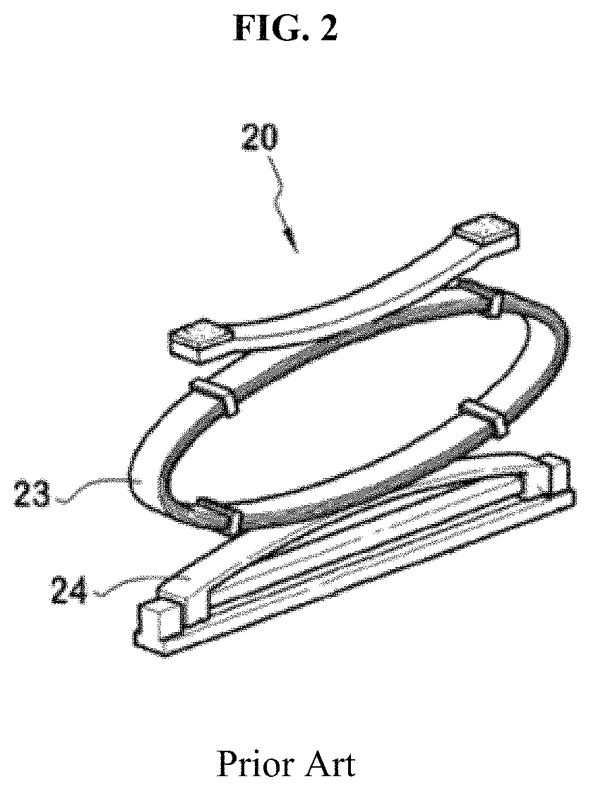
Korean Laid-Open Patent No. 10-2009-0049982 with the above-described construction was problematic in that the flexible members 23 and flexible links 24 lose their flexibility over a long period of use and therefore cannot function properly, thus resulting in a much less comfortable ride due to vibration.

Method used


Image

  • Wheel and airless tire assembly
  • Wheel and airless tire assembly
  • Wheel and airless tire assembly

Examples


Embodiment Construction

[0028]An airless tire according to the present invention prevents a tread part from peeling off the outer wheel as it comes into contact with the road surface during rotation or driving, gives a more comfortable ride by minimizing shocks and rattles caused by an irregular road surface during driving, allows for replacement of broken or damaged components of the tire, and enhances safety and stiffness. An airless tire according to an exemplary embodiment of the present invention will be described below with reference to the accompanying drawings.

[0029]Below is an airless tire according to an exemplary embodiment of the present invention.

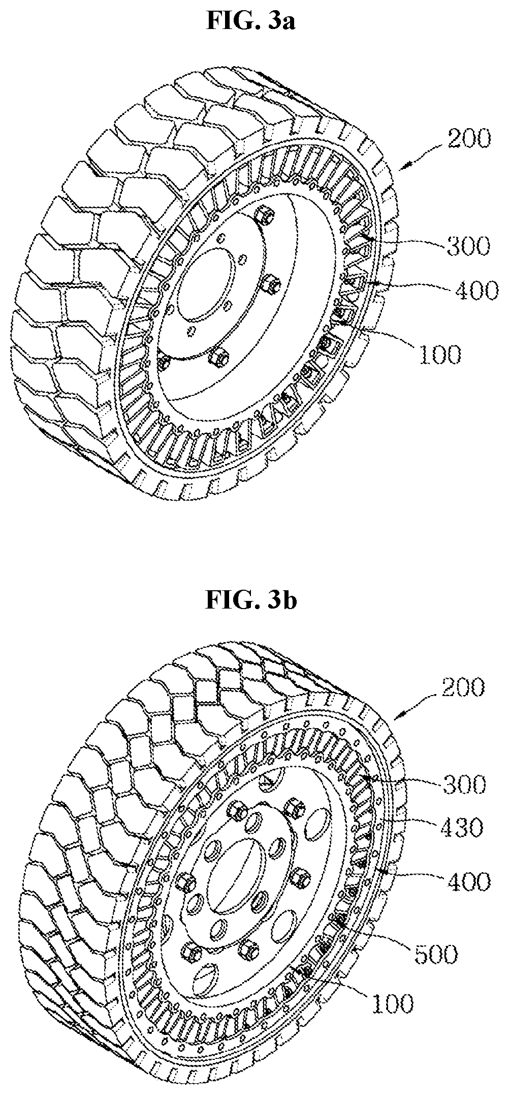
[0030]An airless tire according to the present invention is mainly installed and used on forklifts and industrial, agricultural, mining, and construction applications. The airless tire basically includes a cylindrical inner wheel 100 where the axle of the wheel is mounted through the center, a cylindrical outer wheel 200 mounted to receive the inner w...


PUM


Abstract

An airless tire includes an inner wheel including flanges having fin fastening holes, an outer wheel receiving the inner wheel and including a tread part molded into the outer surface of a drum with at least one of through holes and irregularities to be united with the drum, with the inner periphery of the tread part embedded in the through holes or irregularities, a middle wheel including elastomers, a peripheral part having fin fastening holes and formed on the inner periphery of the elastomers, and ribs in the middle of the elastomers, a fixing device attaching the inside of the outer wheel to the outside of the middle wheel and then detachably uniting the middle wheel and the outer wheel, and coupling fins that allow the inner wheel and the middle wheel to be detachably held together by being inserted through the fin fastening holes and the fin fastening holes.

Description

CROSS REFERENCE TO RELATED APPLICATIONS AND CLAIM OF PRIORITY[0001]This application claims benefit under 35 U.S.C. 119(e), 120, 121, or 365(c), and is a National Stage entry from International Application No. PCT / KR2017 / 009973 filed on Sep. 12, 2017, the entire contents of which are incorporated herein by reference.FIELD OF THE INVENTION[0002]The present invention relates to an airless tire mainly used on forklifts and industrial, agricultural, mining, and construction applications, that prevents a tread part from peeling off the outer wheel as it comes into contact with the road surface during rotation or driving, gives a more comfortable ride by minimizing shocks and rattles caused by an irregular road surface, and improves the durability of the outer wheel.RELATED ART[0003]The tread parts of most tires are inflatable tread parts which are inflated with air pressure as the inside of the tread part or a tube inside the tread part fills with air. A tread part of this type needs to b...

Claims


Application Information

Patent Timeline
Patent Type & Authority Patents(United States)
IPC IPC(8): B60C7/18B60B9/02B60C7/26
CPCB60C7/18B60B9/02B60C7/26B60B25/00B60B21/02B60B19/00B60B2900/523B60C7/102B60C7/20B60C7/24B60C11/11B60C2200/065B60C2200/06B60C2200/08B60C7/146B60C7/107
Inventor LEE, SUNG KEE
Owner LEE SUNG KEE
Learn More