Antenna element
a technology of antenna elements and elements, applied in the field of antennas, can solve the problems of reducing the efficiency of horizontal high-frequency radiation produced by the monopole, generating a horizontally polarized signal in close proximity,
- Summary
- Abstract
- Description
- Claims
- Application Information
AI Technical Summary
Benefits of technology
Problems solved by technology
Method used
Image
Examples
second embodiment
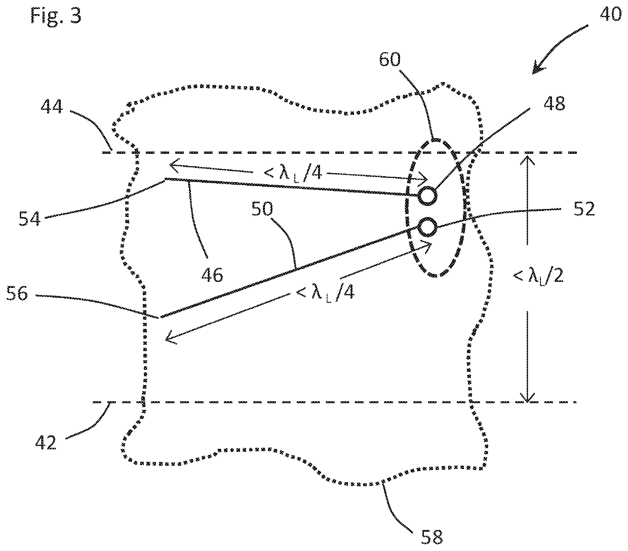
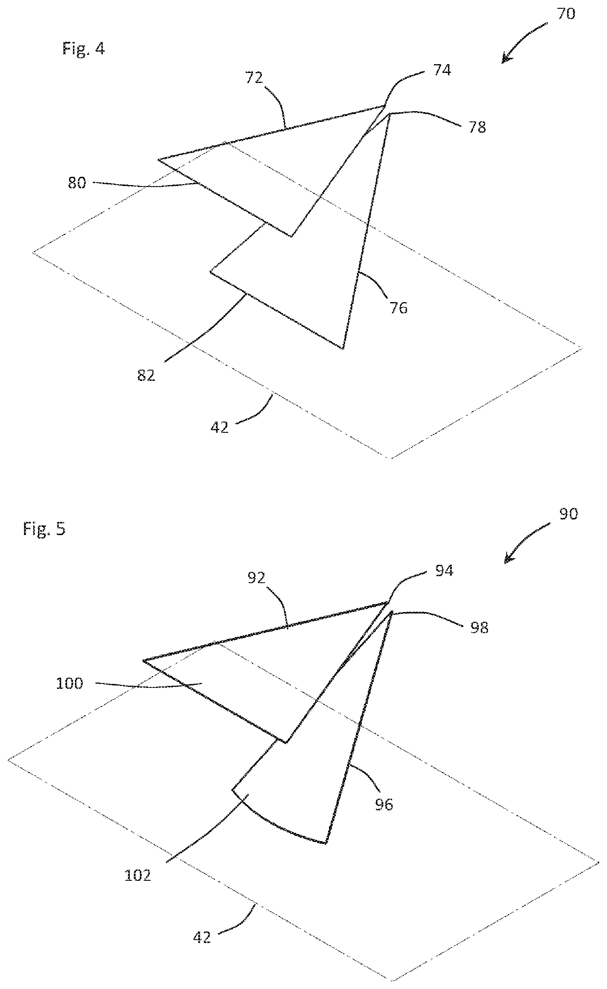
[0026]With reference to FIG. 4, an antenna element 70 (hereinafter “element 70”) is described. The element 70 includes a planar radiator 72 with a radiator feed location 74 and a planar counterpoise 76 with a counterpoise feed location 78. The element 70 has at least one cross-section defined by a plane that is perpendicular to the imaginary ground plane 42 and passes through a location that corresponds to location 60 (element 40) and encompasses the radiator feed location 74 and the counterpoise feed location 78 (such as the imaginary plane 58 in FIG. 3) that satisfies the constraints noted with respect to element 40. More specifically, (a) the cross-section of the radiator 72 extends from the radiator feed location 74 to whatever terminal end is defined by the cross-section (some point along edge 80) and has a straight-line length of less than λl / 4, (b) the cross-section of the counterpoise 76 extends from the counterpoise feed location 78 to whatever terminal end is defined by th...
third embodiment
[0027]With reference to FIG. 5, an antenna element 90 (hereinafter “element 90”) is described. The element 90 includes a planar radiator 92 with a radiator feed location 94 and a partially conic counterpoise 96 with a counterpoise feed location 98. The element 90 has at least one cross-section defined by a plane that is perpendicular to the imaginary ground plane 42 and passes through a location that corresponds to location 60 (element 40) and encompasses the radiator feed location 94 and the counterpoise feed location 98 (such as the imaginary plane 58 in FIG. 3) that satisfies the constraints noted with respect to element 40. More specifically, (a) the cross-section of the radiator 92 extends from the radiator feed location 94 to whatever terminal end is defined by the cross-section (some point along 100) and has a straight-line length of less than λl / 4, (b) the cross-section of the counterpoise 96 extends from the counterpoise feed location 98 to whatever terminal end is defined ...
fourth embodiment
[0028]With reference to FIG. 6, an antenna element 110 (hereinafter “element 110”) is described. The element 110 includes a radiator 112 and a radiator feed location 114 and a planar counterpoise 116 with a counterpoise feed location 118. The radiator 112 is a composite radiator that include a planar section 113A and a curved section 113B that provides capacitive loading, which extends the low-end frequency performance of the element. The element 110 has at least one cross-section defined by a plane that is perpendicular to the imaginary ground plane 42 and passes through a location that corresponds to location 60 (element 40) and encompasses the radiator feed location 114 and the counterpoise feed location 118 (such as the imaginary plane 58 in FIG. 3) that satisfies the constraints noted with respect to element 40. More specifically, (a) the cross-section of the radiator 112 extends from the radiator feed location 114 to whatever terminal end is defined by the cross-section (some ...
PUM
 Abstract
Description
Claims
Application Information
 - R&D
- Intellectual Property
- Life Sciences
- Materials
- Tech Scout
- Unparalleled Data Quality
- Higher Quality Content
- 60% Fewer Hallucinations
Browse by: Latest US Patents, China's latest patents, Technical Efficacy Thesaurus, Application Domain, Technology Topic, Popular Technical Reports.
© 2025 PatSnap. All rights reserved.Legal|Privacy policy|Modern Slavery Act Transparency Statement|Sitemap|About US| Contact US: help@patsnap.com


