
Position based vibration reduction of nacelle movement

a technology of vibration reduction and nacelle movement, applied in the direction of wind energy generation, mechanical equipment, machines/engines, etc., can solve the problem of risk of undesired coupling in tall and/or soft towers

Active Publication Date: 2022-07-26
VESTAS WIND SYST AS
View PDF19 Cites 0 Cited by
  • Summary
  • Abstract
  • Description
  • Claims
  • Application Information

AI Technical Summary

Benefits of technology

This approach effectively reduces nacelle vibrations in the fore-aft direction, particularly in tall and / or soft towers, by generating a stabilization effect that limits self-induced resonances and improves control strategy robustness.

Problems solved by technology

In particular, there is a risk of an undesired coupling in tall and / or soft towers.

Method used


Image

  • Position based vibration reduction of nacelle movement
  • Position based vibration reduction of nacelle movement
  • Position based vibration reduction of nacelle movement

Examples


Embodiment Construction

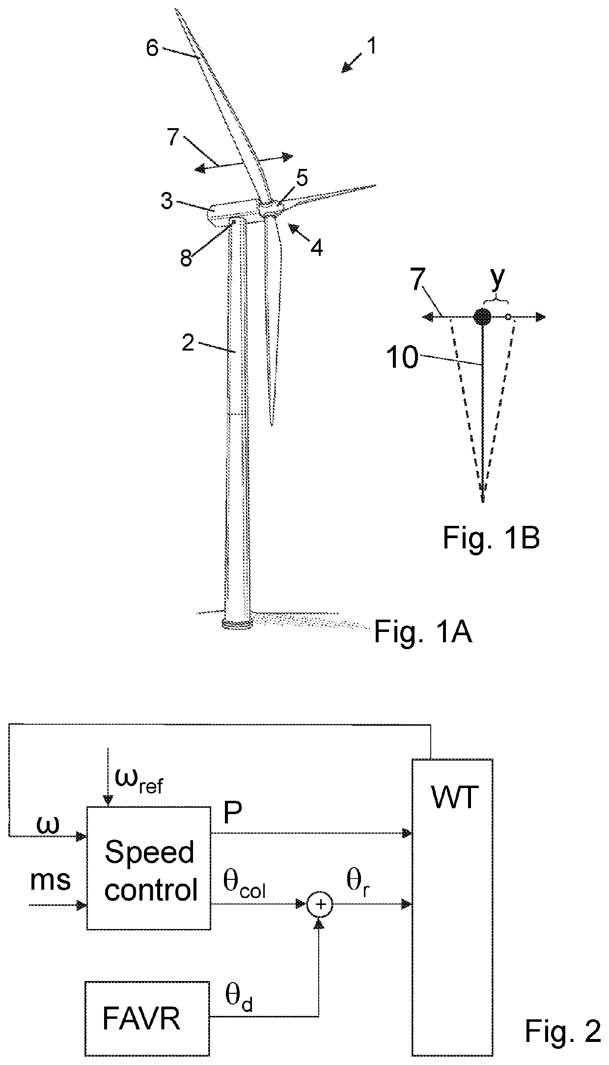
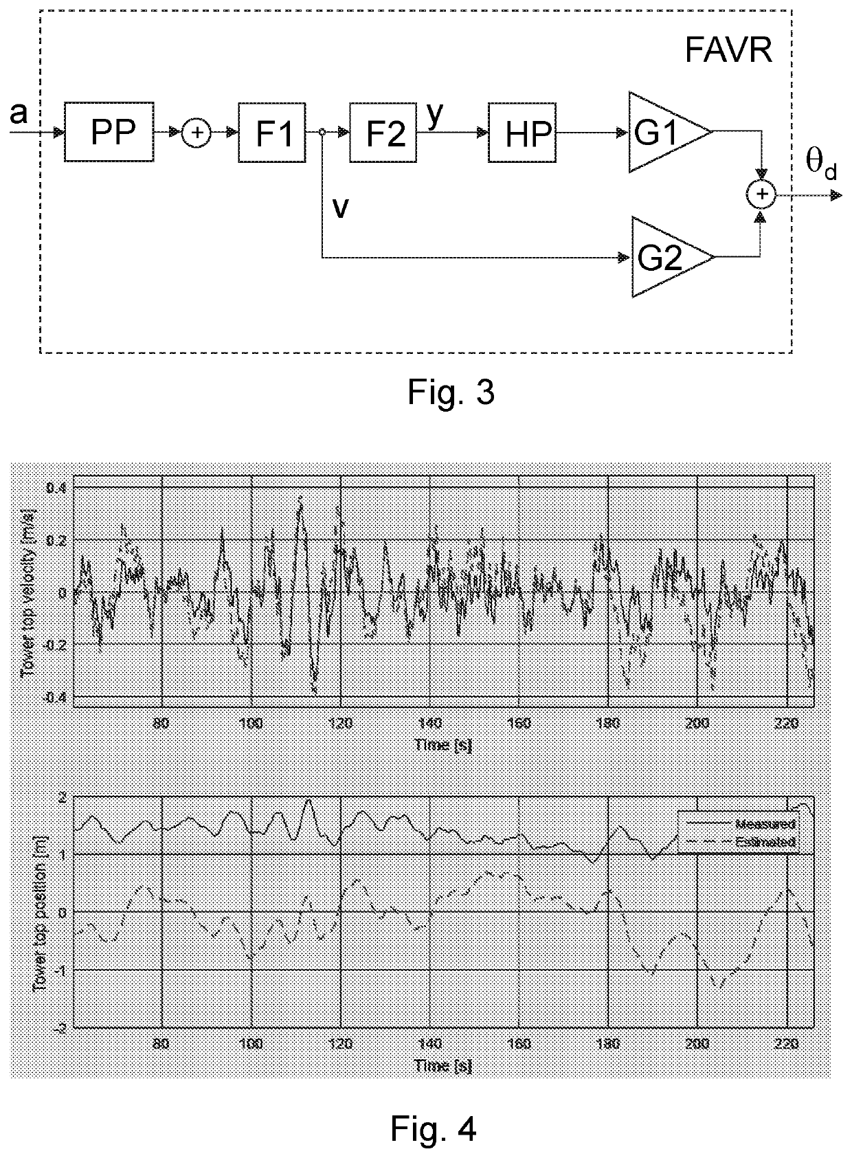
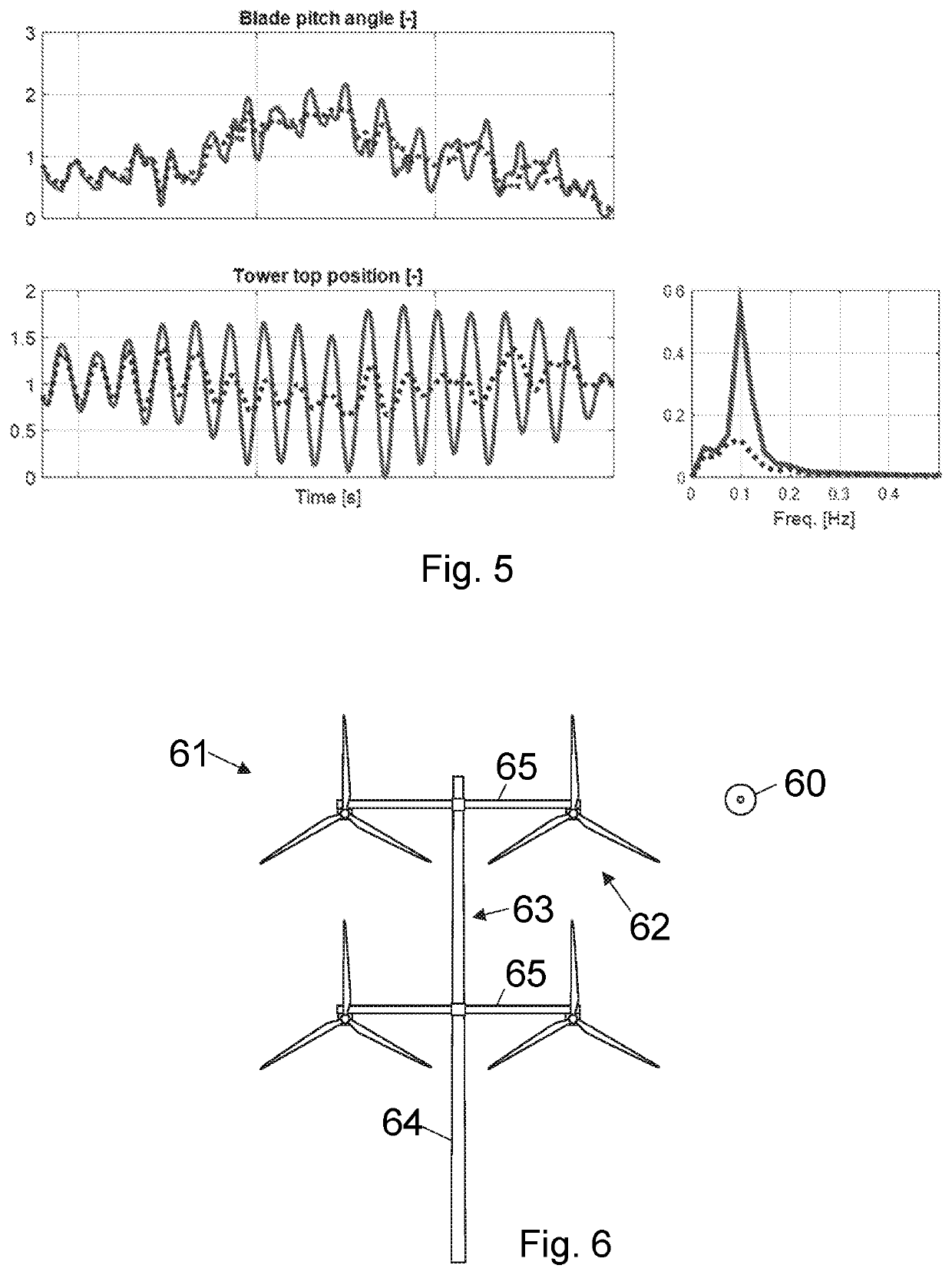
[0030]FIG. 1A illustrates, in a schematic perspective view, an example of a wind turbine 1. The wind turbine 1 includes a tower 2, a nacelle 3 disposed at the apex of the tower, and a rotor 4 operatively coupled to a generator housed inside the nacelle 3. In addition to the generator, the nacelle houses miscellaneous components required for converting wind energy into electrical energy and various components needed to operate, control, and optimize the performance of the wind turbine 1. The rotor 4 of wind turbine includes a central hub 5 and a plurality of blades 6 that project outwardly from the central hub 5. In the illustrated embodiment, the rotor 4 includes three blades 6, but the number may vary. Moreover, the wind turbine comprises a control system. The control system may be placed inside the nacelle or distributed at a number of locations inside (or externally to) the turbine and communicatively connected. The rotor blades are pitch-adjustable. The rotor blades may at least...


PUM


Abstract

The present invention relates to control of a wind turbine where nacelle vibration is reduced by use of blade pitching. The nacelle vibrations are reduced based on a position signal of the nacelle. A pitch signal is determined based on the position signal and applied to the pitch-adjustable rotor blades in order to reduce nacelle vibration.

Description

FIELD OF THE INVENTION[0001]The present invention relates to control of a wind turbine where nacelle vibration is reduced by use of blade pitching.BACKGROUND OF THE INVENTION[0002]Wind turbines as known in the art comprises a wind turbine tower supporting a nacelle and a rotor with a number of pitch-adjustable rotor blades. An exemplary wind turbine is a horizontal axis wind turbine with a nacelle positioned at the tower top, but also multi-rotor structures are known, such as a multi-rotor turbine with nacelles positioned at a tower structure in the form of one or more support arms extending from a central tower structure.[0003]A wind turbine is prone vibrations since it comprises a large mass placed at the end of a slender tower or tower structure. These vibrations include nacelle movement in the lateral direction as well as in the fore-aft direction. It is known in the art that the vibrations can be damped by actively pitching of the blades to generate counter forces to reduce the...

Claims


Application Information

Patent Timeline
Patent Type & Authority Patents(United States)
IPC IPC(8): F03D7/02F03D7/04
CPCF03D7/0296F03D7/0224F03D7/042F05B2260/96F05B2270/327F05B2270/807F05B2270/309F05B2270/334Y02E10/72
Inventor CAPONETTI, FABIOTHOMSEN, JESPER SANDBERG
Owner VESTAS WIND SYST AS
Learn More