
Engine system operating strategy apportioning fuel injection between upstream and downstream injection locations

a technology of engine system and fuel injection, which is applied in the direction of charge feed system, electric control, combustion-air/fuel-air treatment, etc., can solve the problems that alcohol fuel in liquid form can have various deleterious effects on engine operation and performance, and the known strategy cannot achieve sufficient alcohol quantity to satisfy engine load demands

Active Publication Date: 2022-07-12
CATERPILLAR INC
View PDF11 Cites 1 Cited by
  • Summary
  • Abstract
  • Description
  • Claims
  • Application Information

AI Technical Summary

Benefits of technology

This patent describes a method and system for injecting liquid fuel into compressed air in an engine. The system includes a compressor, a manifold, and multiple fuel injectors located downstream from the injector. The system monitors the temperature of the air and uses a control unit to apportion the amount of fuel injected between the upstream and downstream locations based on the temperature. This technology allows for precise control of fuel injection and better engine performance.

Problems solved by technology

As a result it can be challenging in some instances to vaporize liquid alcohol fuels to a desired extent, resulting in dripping or dribbling of liquid alcohol fuel at certain points in an engine system.
Ultimately, known strategies can fail to vaporize sufficient alcohol quantities to satisfy engine load demands.
Moreover, alcohol fuel in liquid form can have various deleterious effects on engine operation and performance.

Method used


Image

  • Engine system operating strategy apportioning fuel injection between upstream and downstream injection locations
  • Engine system operating strategy apportioning fuel injection between upstream and downstream injection locations

Examples


Embodiment Construction

[0009]Referring to FIG. 1, there is shown an internal combustion engine system 10, according to one embodiment. Engine system 10 includes an internal combustion engine 12 having an engine housing 14 with a plurality of combustion cylinders 16 formed therein. A plurality of pistons 18 are positioned within combustion cylinders 16 and movable between a bottom dead center position and a top dead center position to rotate a crankshaft 20 in a generally conventional manner. An engine head 22 is attached to engine housing 14 and supports engine valves 24 movable to control fluid connections between combustion cylinders 16 and an exhaust manifold 26 and an intake manifold 30 in an intake system 28. Engine 12 can operate in a four-stroke engine cycle, or potentially a two-stroke engine cycle, for example. Pistons 18 and combustion cylinders 16 can include any number of pistons and cylinders in any suitable arrangement such as an inline pattern, a V-pattern, or still another. Example applica...


PUM


Abstract

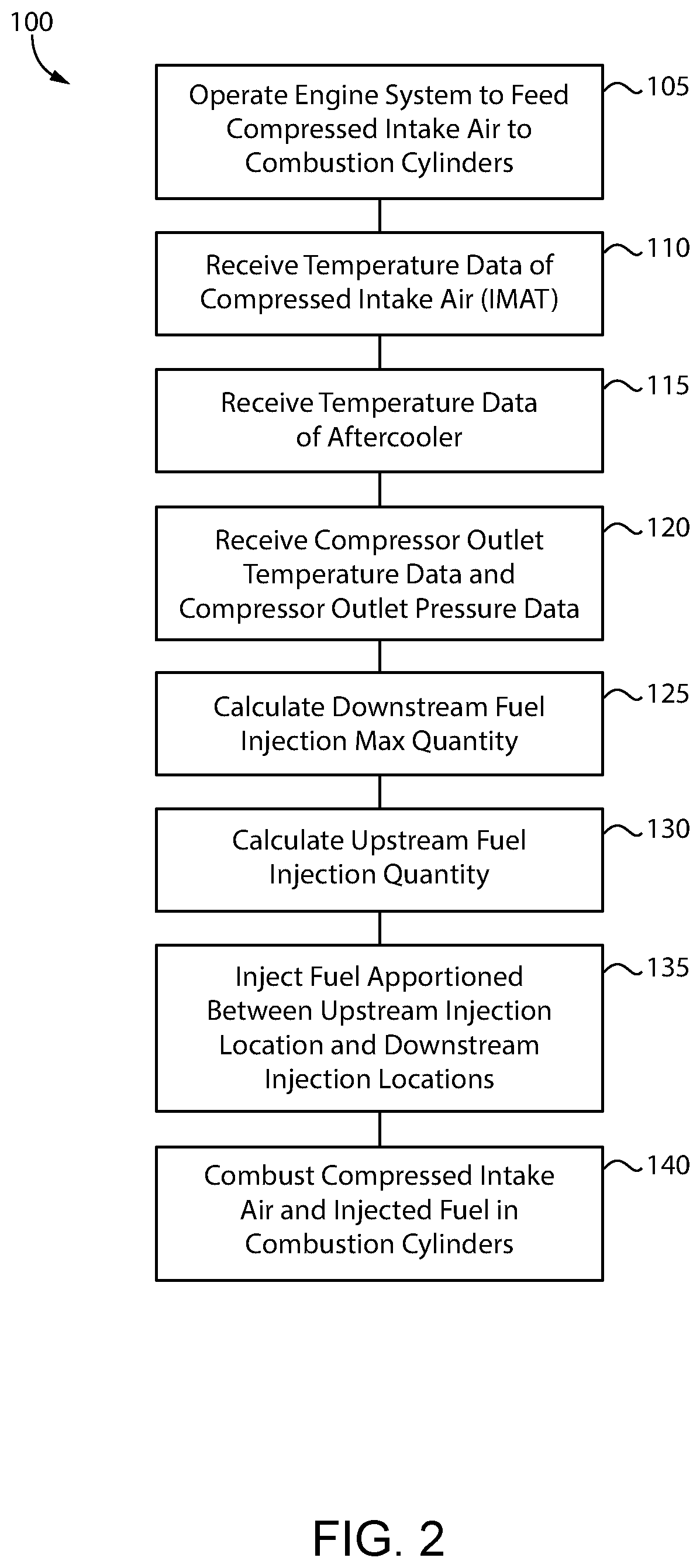
Operating an engine includes injecting a liquid alcohol fuel such as methanol into a stream of compressed intake air at an upstream injection location, and injecting the liquid fuel at a plurality of downstream injection locations into a plurality of streams of the compressed intake air from an intake manifold to combustion cylinders in the engine. A fueling control unit apportions a total injected quantity of the liquid fuel between the upstream injection location and the plurality of downstream injection locations based on a temperature parameter of the compressed intake air. The compressed intake air is combusted with the liquid fuel and a compression ignition pilot fuel in the plurality of combustion cylinders.

Description

TECHNICAL FIELD[0001]The present disclosure relates generally to operating an internal combustion engine, and more particularly to apportioning liquid fuel between an upstream injection location and a plurality of downstream injection locations based on a temperature parameter of compressed intake air.BACKGROUND[0002]Internal combustion engines are widely used throughout the world for purposes ranging from electrical power generation to land vehicle and marine vessel propulsion, pumps, compressors, and a great many different industrial applications. Internal combustion engines can operate on a variety of different liquid fuels, gaseous fuels, and various blends. Spark-ignited engines employ an electrical spark to initiate combustion of fuel and air, whereas compression ignition engines typically compress gases in a cylinder to an autoignition threshold such that ignition of fuel begins without requiring a spark. In well-known pilot-ignited strategies, including dual fuel strategies,...

Claims


Application Information

Patent Timeline
IPC IPC(8): F02D41/30F02D19/06F02M35/104F02M31/20
CPCF02D41/30F02D19/0655F02D19/0694F02M31/20F02M35/104F02D2200/0414F02D2200/0614F02D41/3094F02D19/081F02D19/0689F02D19/0692F02D41/0007F02D2200/0406
Inventor SCHROEDER, ERIC LEEMONTGOMERY, DAVID TODDKIM, ARNOLD MYOUNGJINBARDELL, MICHAELLANDIN, NIKOLAS KARLSVENSSON, KENTH I.
Owner CATERPILLAR INC
Learn More