Gripper for spools

a spool and spool technology, applied in the field of spool grippers, can solve the problems of complex and dynamic production environment, time-consuming location of the centre, and use of relatively expensive ccd cameras

Active Publication Date: 2022-06-21
NV BEKAERT SA
View PDF18 Cites 0 Cited by
  • Summary
  • Abstract
  • Description
  • Claims
  • Application Information

AI Technical Summary

Benefits of technology

[0012]The main object of the invention is to eliminate the described drawbacks of the prior art: too expensive equipment and / or too slow determinations of the centre of a hole. A second object is to provide algorithms, methods that allow for a fast and reliable determination of the bore hole of a spool. The methods are used to locally guide a spool gripper towards a spool and clamp it in a fast and reliable way. A third object is to provide a gripper that is particularly suitable to find and grip spools in an industrial environment.
[0017]The sensors are ‘presence-absence detectors’ and can for example be based on the reflection of light. The sensor emits a collimated light beam and also detects the light reflected by a body obstructing the light beam. Typically laser or collimated LED light can be used to this end possibly frequency modulated to increase the detection limit. Possibly the sensor may be able to detect the distance from the sensor to the reflecting body but this makes the sensor more expensive. The wavelength used can be in the infrared, the visible or the ultraviolet spectrum. Visible light has the advantage that the beam spots become visible to the human eye on the spool as the gripper moves.
[0022]The perpendicular distance ‘d’ in the reference plane between the reference axis and the line formed by said two or more sensors is by preference less than the clamp size. In this way the movement of the gripper—once the centre position of the grip part is identified—is reduced to a minimum. This has the advantage that the centre of the spool is readily located and less time is lost in clamp movement. Alternatively this perpendicular distance should be larger than half of the diameter of the grip part in order to prevent that the gripper must move back after having identified the centre position of the grip part.
[0024]When the circular grip part of the spool is the spool flange, the clamp can be provided with spring mounted, grooved, circular segments that hold the flange when slid over the flange. The clamp size is then equal to the diameter of the circle formed by the grooved circular segments when closed i.e. equal to the flange diameter. For removal of the clamp, the circular segments are radially moved thereby liberating the flange.
[0050]An advantage of the gripper is that the sensors go before the clamp. Hence, no backward movement of the gripper is needed (unless the limited travel length is reached). This prevents back-and-forth movements that may confuse the location tracking of the controller due to acceleration forces.

Problems solved by technology

When automating the task of picking up a full or empty spool engineers are confronted with a complex and dynamic production environment.
Such methods require the use of CCD cameras that are relatively expensive.
This makes the location of the centre time-consuming as a meandering path must be followed.

Method used


Image

  • Gripper for spools
  • Gripper for spools
  • Gripper for spools

Examples


Embodiment Construction

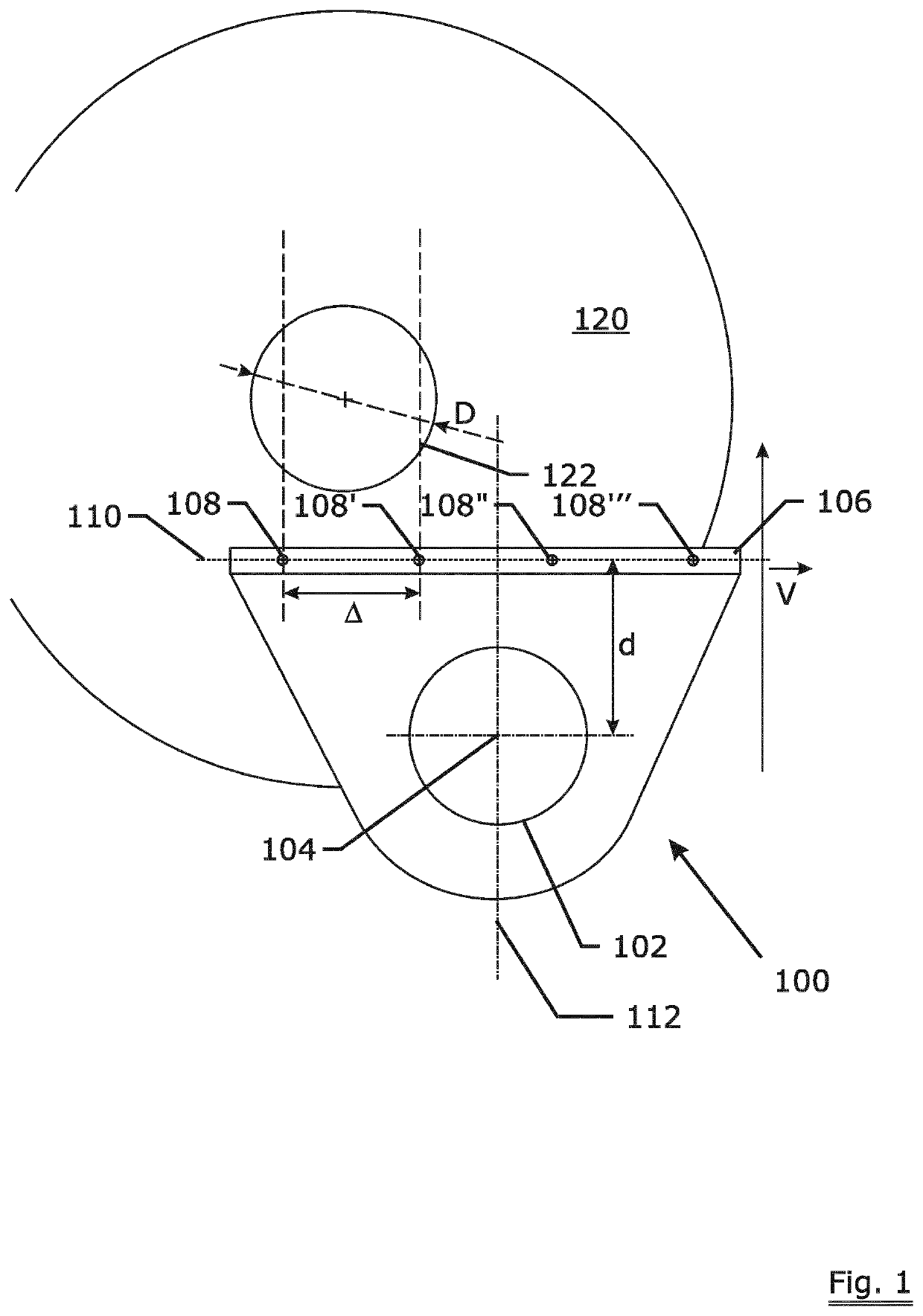
[0057]FIG. 1 shows a view from above of a general embodiment of the gripper 100. The gripper comprises a driveable clamp 102 that is mounted on an arm of a robot or automatically guided vehicle or similar device (not shown). The clamp 102 has a reference axis indicated with 104 that is in this case perpendicular to the plane of the sheet. The spool to be gripped is shown as 120 and has a circular grip part 122 that is in this case the bore hole of the spool 120. The circular grip part 122 has a diameter indicated with ‘D’. The clamp size—corresponding to the diameter of the clamp 102—is thus slightly less than D in order to allow insertion of the clamp into the bore hole. The gripper has a scanning system 106 comprising four sensors indicated with 108, 108′, 108″, 108′″ on a line 110. The sensors are separated from one another by a distance ‘Δ’. The distance A is just less than D / 2 for example 0.45×D. The sensors sense the presence or absence of the spool body 120 in a direction par...


PUM


Abstract

A gripper for finding, clamping and releasing spools having a circular grip part such as a flange or a bore hole as well as a method to operate such gripper. The gripper has a driveable clamp that is provided with a scanning system comprising ‘presence-absence detectors’ that detect the presence or the absence of the circular grip part. The gripper is slowly moved over the flange of the spool and by means of the detectors and some calculation the centre of the grip part is identified followed by the gripping of the spool. The gripper has the advantage that no back-and-forth movement is needed in order to locate the circular grip part and that the superfluous motion of the gripper is prevented.

Description

TECHNICAL FIELD[0001]The invention relates to a gripper for finding, clamping and releasing spools. The gripper enables the automated handling of spools in an industrial environment.BACKGROUND ART[0002]In the production of elongated articles such as yarns, threads, ropes, cords, steel cords and the like final and intermediate products are carried on spools. The number of times a spool is picked up to make for example one final spool of a simple steel cord construction like 7×7 easily rises above hundred as not only the full spools have to be picked up but also the empty ones have to be removed. Therefore the making of the mentioned articles to a large extent reduces to the activity of picking up, moving and placing empty and full spools. There is therefore a constant desire to reduce this number of handlings e.g. by increasing the capacity of those spools or to automate the handling in order to eliminate this tedious and labour intensive task.[0003]When automating the task of pickin...

Claims


Application Information

Patent Timeline
Patent Type & Authority Patents(United States)
IPC IPC(8): B25J9/16B25J15/00B25J13/08B65H67/06
CPCB25J9/1612B25J9/1653B25J9/1694B25J13/08B25J15/0028B25J15/0047B65H67/065B65H2701/35B65H2701/31
Inventor HUGELIER, JOHAN
Owner NV BEKAERT SA
Why Eureka
Try Eureka