
Potential drop compensated electro-optic device

a technology of electro-optic devices and potential drops, applied in the field of electro-optic devices, can solve the problem that the potential supplied by the power source (i.e. the drive potential) does not equal the potential, and achieve the effect of substantially reducing the disadvantages and eliminating the problems of operating an electro-optic device in the pas

Active Publication Date: 2022-06-14
GENTEX CORP
View PDF4 Cites 0 Cited by
  • Summary
  • Abstract
  • Description
  • Claims
  • Application Information

AI Technical Summary

Benefits of technology

The present invention improves the operation of electro-optic devices by reducing or eliminating problematic issues. One technical effect is the compensation for electrical potential drops, which ensures more accurate and constant activation of the electro-optic medium. In simple terms, this patent makes devices work better and more reliably.

Problems solved by technology

However, the electrical potential supplied by the power source (i.e. the drive potential) does not equal the potential actually delivered to the electro-optic medium (i.e. the EO potential).

Method used


Image

  • Potential drop compensated electro-optic device
  • Potential drop compensated electro-optic device
  • Potential drop compensated electro-optic device

Examples


Embodiment Construction

[0015]For the purposes of description herein, the specific devices and processes illustrated in the attached drawings and described in this disclosure are simply exemplary embodiments of the inventive concepts defined in the appended claims. Hence, specific dimensions and other physical characteristics relating the embodiments disclosed herein are not limiting, unless the claims expressly state otherwise.

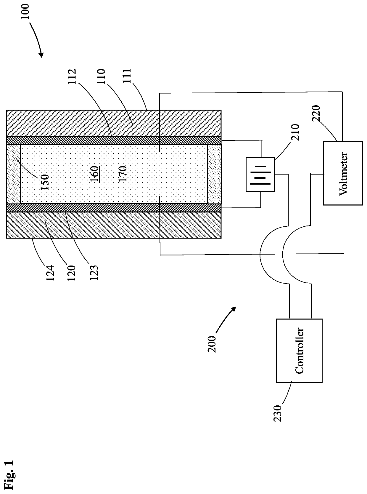
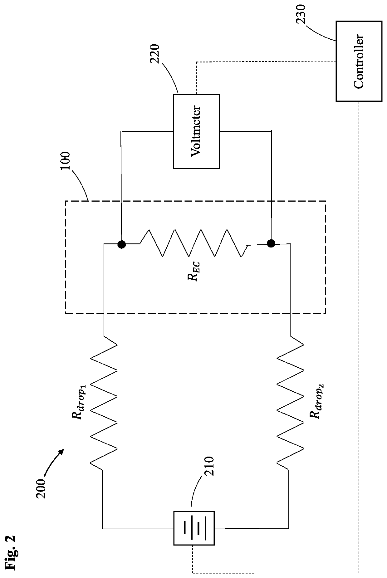
[0016]FIG. 1 is a cross sectional schematic representation of an electro-optic device 100 and an accompanying potential drop compensation system 200. Additionally, FIG. 2 is a corresponding electrical circuit schematic of electro-optic device 100 and the accompanying potential drop compensation system 200. Further, as merely schematic representations, some of the components have been distorted from their actual scale for pictorial clarity.

[0017]Electro-optic device 100, as shown in FIG. 1 and represented by the dashed box in FIG. 2, for example, may be a mirror, a rearview assembly,...


PUM

PropertyMeasurementUnit
wavelengthsaaaaaaaaaa
electrical potentialaaaaaaaaaa
impedanceaaaaaaaaaa

Abstract

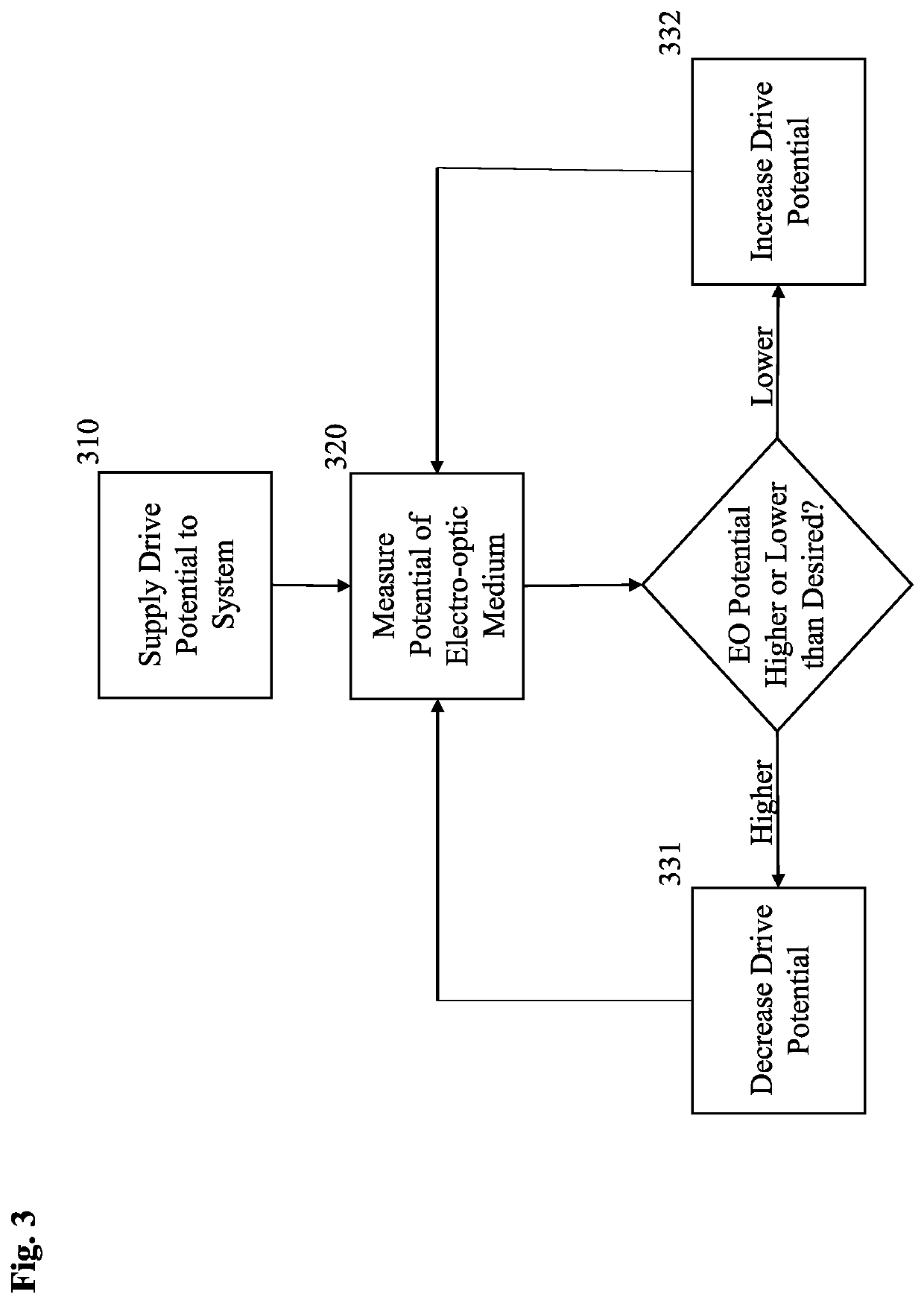
An electro-optic system where an electrical potential is changed and / or regulated to achieve a desired potential applied to an electro-optic medium. The electro-optic system comprises an electro-optic medium disposed in a chamber defined in part by two electrodes. A power source is connected to the two electrodes and thereby operable to apply an electrical potential to the electrochromic medium across the two electrodes. A voltmeter is operable to measure an electrical potential between two points within the chamber. Additionally, a controller is connected to the voltmeter and the power source and is operable to regulate the electrical potential applied by the power source based, at least in part, on the electrical potential measured between the two points within the chamber by the voltmeter.

Description

CROSS-REFERENCE TO RELATED APPLICATIONS[0001]This application claims priority under 35 U.S.C. § 119(e) to U.S. Provisional Application No. 62 / 896,223 filed on Sep. 5, 2019, entitled “POTENTIAL DROP COMPENSATED ELECTROCHROMIC DEVICE,” the disclosure of which is hereby incorporated by reference in its entirety.FIELD OF INVENTION[0002]The present invention relates in general to electro-optic devices and, more particularly, to applying an electrical potential to an electro-optic medium in an electro-optic device.BACKGROUND OF INVENTION[0003]Electro-optic devices are well known. When a sufficient electrical potential is applied across a pair of electrodes, an electro-optic medium, disposed between the electrodes, becomes activated. Some electro-optic devices are electrochromic and accordingly, when activated, change their color and / or light transmissivity. Taking advantage of this, devices such as dimmable mirrors and windows have become increasingly popular in industries such as automot...

Claims


Application Information

Patent Timeline
Patent Type & Authority Patents(United States)
IPC IPC(8): G02F1/153G02F1/03G09G3/19G09G3/38G02F1/163B60J3/04B60R1/02
CPCG02F1/163B60J3/04B60R1/02B60R1/088
Inventor NIU, XIAOXUHEINTZELMAN, ADAM R.GEERLINGS, KURTIS L.
Owner GENTEX CORP
Learn More