Eureka AIR delivers breakthrough ideas for toughest innovation challenges, trusted by R&D personnel around the world.

Roll induced four wheel steering vehicle

a four-wheel steering and steering wheel technology, applied in vehicle springs, resilient suspensions, vehicle components, etc., can solve the problems of unwanted sway, negative effect of allowing bump forces from one side of the vehicle to be transferred to the other side, and the driver of such vehicle naturally has a tendency to tilt the head, so as to reduce the centrifugal force experienced by the driver

Active Publication Date: 2022-06-14
MAINVILLE MICHAEL J
View PDF12 Cites 2 Cited by
  • Summary
  • Abstract
  • Description
  • Claims
  • Application Information

AI Technical Summary

Benefits of technology

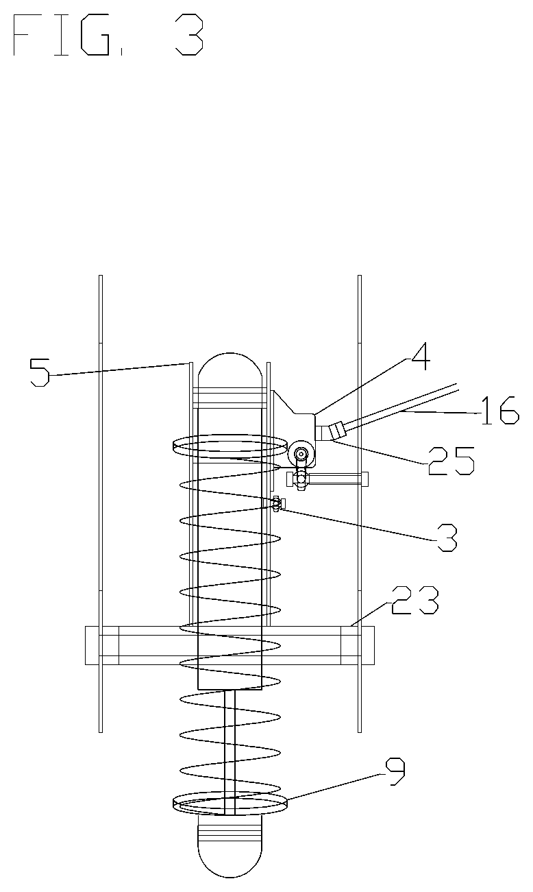
[0005]The subject invention and embodiments comprises of a method and apparatus for a four wheel roll steering device with four wheel independent suspension. The invention employs a frame system and independent suspension links, pivotally connected to the wheel assemblies. Furthermore, the subject invention and its embodiments are supported by a mechanically pivoting shock mount, providing both steering control and suspension attachment for the shock and spring. By mechanically rolling the entire chassis of the vehicle laterally into the turn, centrifugal forces experienced by the driver are reduced, resulting in a feeling of integration and comfort even in adverse terrain.

Problems solved by technology

Prior art design UTV's have provided good performance over rough surfaces, or smooth turns, but can be uncomfortable when rough surfaces are encountered while turning or when turning sharply at high speed.
Centrifugal forces developed during such a turn cause the vehicle to roll outward opposite the direction of the turn, creating unwanted sway.
This however has a negative effect allowing bump forces from one side of the vehicle to be transferred to the other side.
During rough or high speed turns, the driver of such vehicle naturally has a tendency to tilt the head, and lean the body into the turn within the confines of the seat.
Although effective, this can become tiring and uncomfortable after some time resulting in fatigue.

Method used


Image

  • Roll induced four wheel steering vehicle
  • Roll induced four wheel steering vehicle
  • Roll induced four wheel steering vehicle

Examples


Embodiment Construction

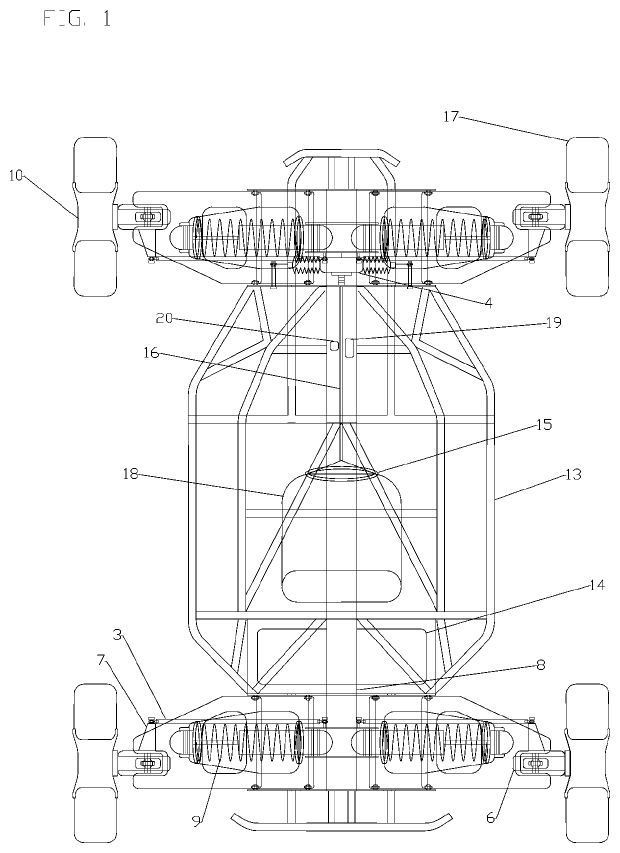
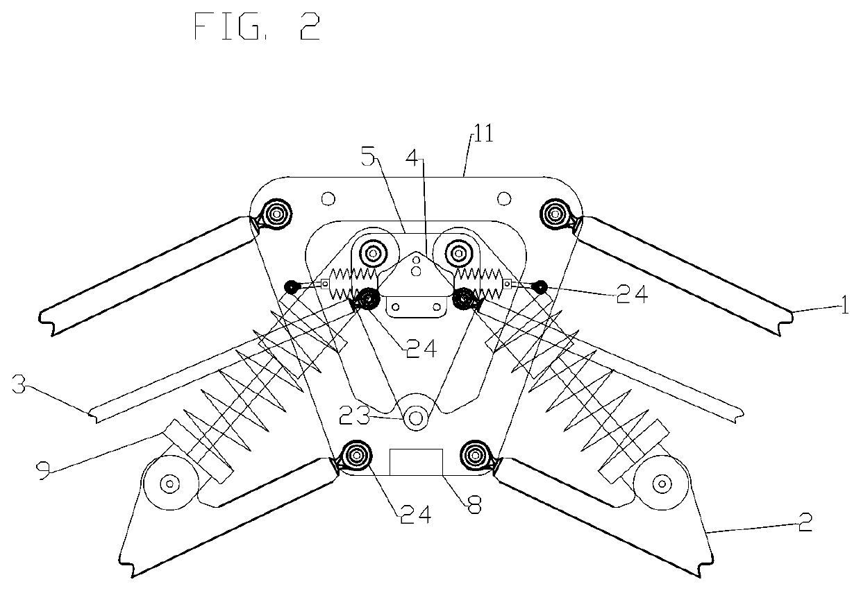
[0012]FIG. 1 illustrates a top view of one embodiment constructed in accordance with teachings of the present invention. This embodiment can be used for entertainment, sport, or transportation. When operating this device, the driver climbs inside the driver's seat (18), and grabs hold of the steering wheel (15) rotates it, causing the rack and pinion steering unit (4) push laterally on the outside portion of the mounting plate (11). Both roll and steering are accomplished simultaneously by turning steering wheel in the direction of the turn. Speed or braking commands are generated by foot controlled accelerator (19) and brake (20) pedals as is common practice in the art. The illustrated device consists of a center chassis rail (8) providing attachment points for mechanical components and a roll cage (13) for the driver. The tire (17) is rotated by a single sided hub motor (10) with spindle (6) that also serves as the wheel. Each wheel is able to move up and down independently to pro...


PUM


Abstract

The four wheel steering vehicle utilizes a cage system that extends along the longitudinal axis to protect the driver coupled to a center rail chassis. Front and Back independent suspension links extend outward along the lateral axis pivotally connected to the wheel assemblies enabling four wheel independent suspension. A centrally located pivoting shock provides both steering control and suspension attachment for the shock and spring. The vehicle is controlled by the driver using a steering wheel, acceleration pedal, and a brake pedal. The invention provides a feeling of integration with the vehicle as the driver rolls into turns with the vehicle, while minimizing fatigue caused by the continuous resistance to centrifugal cornering forces.

Description

FIELD OF THE INVENTION[0001]The invention relates to a vehicle with four wheel steering, four wheel independent suspension, and proportional roll during cornering resulting in an improved driver comfort over adverse terrain.BACKGROUND OF THE INVENTION[0002]Utility task vehicles or UTV's for short are typically used for recreation or transportation. They can be combustion engine or electrically driven. UTV's typically feature 4 large air filled rubber tires. A typical UTV has independent suspension, although some may feature solid axles. Most UTV's rely on front wheel steering similar to what is found in an automobile. They are well documented in the art.[0003]Prior art design UTV's have provided good performance over rough surfaces, or smooth turns, but can be uncomfortable when rough surfaces are encountered while turning or when turning sharply at high speed. Centrifugal forces developed during such a turn cause the vehicle to roll outward opposite the direction of the turn, creat...

Claims


Application Information

Patent Timeline
Patent Type & Authority Patents(United States)
IPC IPC(8): B62D9/00B60G3/26B62D9/04B60G15/06
CPCB62D9/002B60G3/265B60G15/067B62D9/04B60G2202/312B62D9/02B60G2300/07B60G2300/45B60G2300/50B60G2200/44B60G2200/46B60G3/20B60G2200/144B60G2200/445B60G2204/143B60G7/02B60G2204/128B60G2204/129B60G17/0163B60G17/0195B60G2400/39B60G2400/34B60G2400/10B60G2800/014B60G2800/24B60W2300/50
Inventor MAINVILLE, MICHAEL JOHN
Owner MAINVILLE MICHAEL J
Why Eureka
Eureka Blog
Learn More