
Method and an apparatus for determining hemodynamic status

a hemodynamic status and apparatus technology, applied in the field of methods and apparatuses for determining hemodynamic status, can solve the problems of abnormal heart rhythm, rapid heartbeat, and insufficient information obtained from cardiac electrical signals to determine individual conditions, and achieve the effect of maximizing the available data

Active Publication Date: 2022-06-07
View PDF19 Cites 0 Cited by
  • Summary
  • Abstract
  • Description
  • Claims
  • Application Information

AI Technical Summary

Benefits of technology

This approach enhances the reliability of hemodynamic status assessment, reducing the risk of inappropriate therapy delivery and improving the accuracy of determining whether a therapy is needed, thus ensuring safer and more effective treatment for cardiac arrhythmias.

Problems solved by technology

Whilst cardiac electrical signals can be used as an indicator of the individual's condition, under some circumstances the information obtained from the cardiac electrical signal may not be sufficient to determine the individual's condition and hence make a decision on whether a therapy should be delivered by the implantable or externally wearable device or not.
As mentioned above, VT is a type of tachycardia, which causes improper electrical activity of the heart and hence abnormal heart rhythm, often causing a rapid heartbeat.
In the case of a well-tolerated VT, it is highly preferable to delay or even omit the delivery of a therapy, as an unnecessary therapy can be harmful and / or uncomfortable.
For example, sometimes the rapid sequence of electrical impulses (overdrive pacing) can cause VT to deteriorate into a worse form of VT.
As another example, electric shocks (defibrillation) are uncomfortable and may even worsen the long-term function of the heart causing an increased probability of death in the long term.
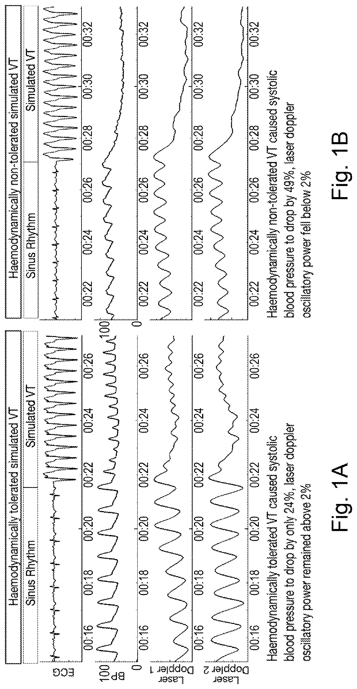
However, it is difficult to distinguish such well tolerated VT from an electrocardiogram (ECG) signal, which is a cardio electrical signal, alone.
As yet another example, an ICD lead which is configured to sense the electrical signal of the heart may be damaged, for example due to fracture.
This may cause noise to be included in the sensed electrical signal, and such noise can be incorrectly interpreted as an arrhythmia (VT or Ventricular Fibrillation (VF)).
In contrast, the BP signal in FIG. 1B drops significantly when VT occurs, which indicates that this VT is not well tolerated and there is not enough cardiac output to ensure that perfusion to the essential major organs are being achieved.
Unfortunately, BP signals are not readily available to implantable or externally wearable devices for constant monitoring.
The problem with such a system is that signals derived from local perfusion data are labile in the presence of the individual's movement, position, placement of the sensor, orientation either within the body or, if externally positioned, the position of the sensor externally.
In particular, if the individual collapses and then twitches (a common occurrence upon fainting) or is shaken by another person, then this motion can generate an artificial fluctuation in the tissue perfusion signal whose frequency may lie in the range of frequencies that might be expected from genuine beating of the heart and therefore may be difficult to distinguish from genuine beating of the heart.
The possibility of this makes the tissue perfusion signal, on its own, an unreliable indicator of whether the patient is genuinely having perfusion of the organs.
As such, regardless of the method used to obtain tissue perfusion signal, currently known methods of sensing and processing of the tissue perfusion signals are prone to being affected by relatively large artificial (“noise”) components hence limiting the reliability and clinical utility of using hemodynamic status derived from the processed perfusion signal.

Method used


Image

  • Method and an apparatus for determining hemodynamic status
  • Method and an apparatus for determining hemodynamic status
  • Method and an apparatus for determining hemodynamic status

Examples


Embodiment Construction

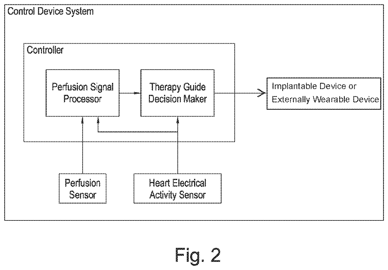
[0065]Many current implantable or externally wearable devices monitor and / or deliver therapies for treating disorders of the cardiac rhythm based on electrical information obtained from the electrical changes that are sensed from the heart. Such electrical activity of the heart represents the heartbeat, but relying solely on this information may not be sufficient to guide therapy reliably as mentioned above.

[0066]Any misguidance of therapy can be particularly harmful where the device is an implantable or externally wearable cardiac defibrillator device which delivers therapy for treating cardiac arrhythmias, because it involves delivering a rapid sequence of electrical stimuli (overdrive pacing) or larger electric shocks (defibrillation) to the heart in an attempt to restore the heart to a normal rhythm. Overdrive pacing can be harmful because sometimes it causes the tachycardia to deteriorate into a faster tachycardia which can worsen the function of the heart. Electric shocks can ...


PUM


Abstract

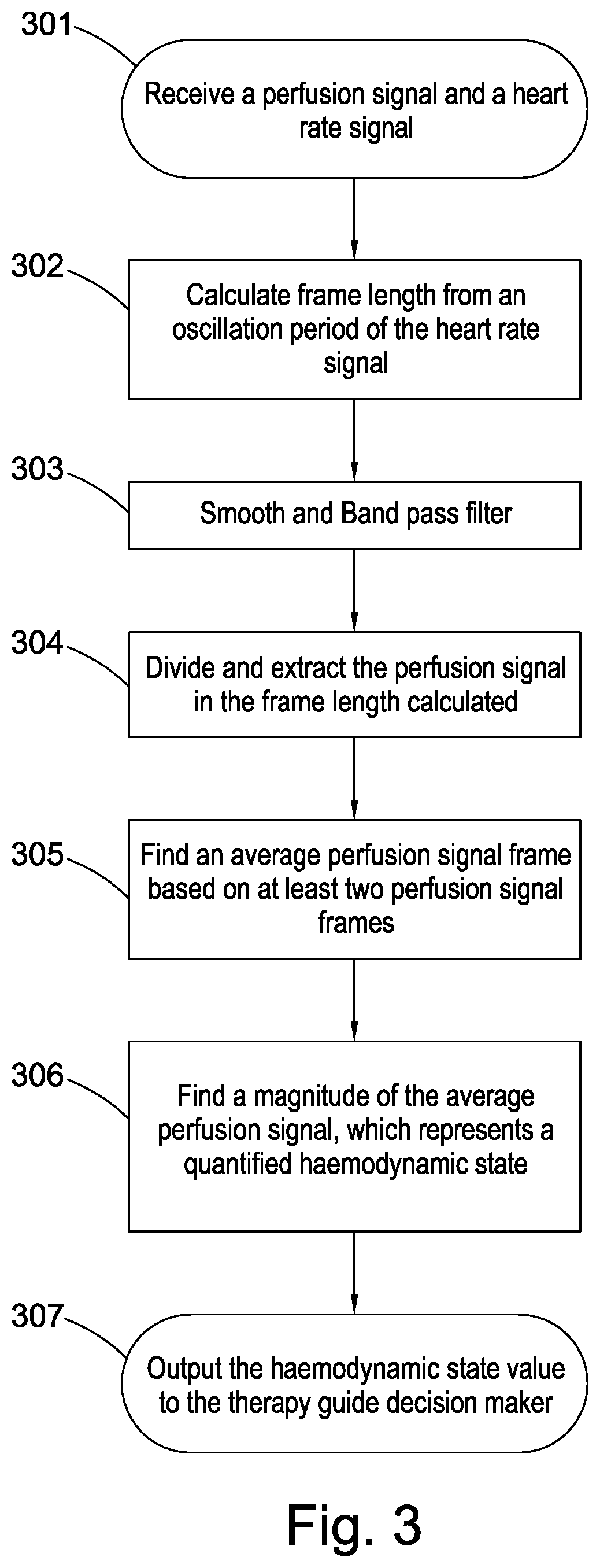
A device and a method thereof for determining a hemodynamic state of an individual from a magnitude of a perfusion signal or a signal which is a measure of a volume of blood in the thoracic cavity of the individual, wherein the control device is configured to receive a first signal and a heart rate signal, divide the first signal into frames, wherein a frame length is determined from an oscillation period of the heart rate signal, and determine a magnitude of the first signal from at least two frames, so as to obtain a more reliable magnitude of the first signal.

Description

PRIORITY APPLICATIONS[0001]This application is a U.S. National Stage Filing under 35 U.S.C. 371 from International Application No. PCT / GB2017 / 050848, filed on Mar. 24, 2017, and published as WO2017 / 163088 on Sep. 28, 2017, which claims the benefit of priority to United Kingdom Application No. 1605111.2, filed on Mar. 24, 2016; the benefit of priority of each of which is hereby claimed herein, and which applications and publication are hereby incorporated herein by reference in their entirety.FIELD OF THE INVENTION[0002]The present invention relates generally to a device for determining a hemodynamic state of an individual from a magnitude of a perfusion signal, a control system comprising a device configured to output a signal to a device for hemodynamic intervention based on a hemodynamic state of an individual determined from a magnitude of a perfusion signal and methods thereof.BACKGROUND OF THE INVENTION[0003]Cardiac arrhythmia are a group of conditions known in the field of car...

Claims


Application Information

Patent Timeline
Patent Type & Authority Patents(United States)
IPC IPC(8): A61B5/02A61B5/00A61N1/39A61N1/365A61N1/37A61B5/318
CPCA61B5/02028A61B5/7203A61N1/36514A61N1/3702A61N1/3904A61N1/3925A61N1/3962A61B5/318A61B5/4836A61B5/7275A61B5/7282A61N1/365
Inventor FRANCISSHUN-SHIN, MATTHEWKEENE, DANIELWHINNETT, ZACHARY
Learn More