Optically conductive filler for laser processing

a filler and laser processing technology, applied in the direction of welding/cutting media/materials, manufacturing tools, welding apparatus, etc., can solve the problems of labor-intensive and difficult coordination of laser energy delivery with laser energy feeding of filler materials during laser welding and cladding

Active Publication Date: 2022-05-31
SIEMENS ENERGY INC
View PDF30 Cites 3 Cited by
  • Summary
  • Abstract
  • Description
  • Claims
  • Application Information

AI Technical Summary

Problems solved by technology

Coordinating the delivery of laser energy with feeding of filler material during laser welding and cladding is challenging.
Powdered filler may be preplaced, but this is labor intensive, is limited to positioning that can be retained by gravity, and is prone to scattering during processing.

Method used


Image

  • Optically conductive filler for laser processing
  • Optically conductive filler for laser processing
  • Optically conductive filler for laser processing

Examples


embodiment 40

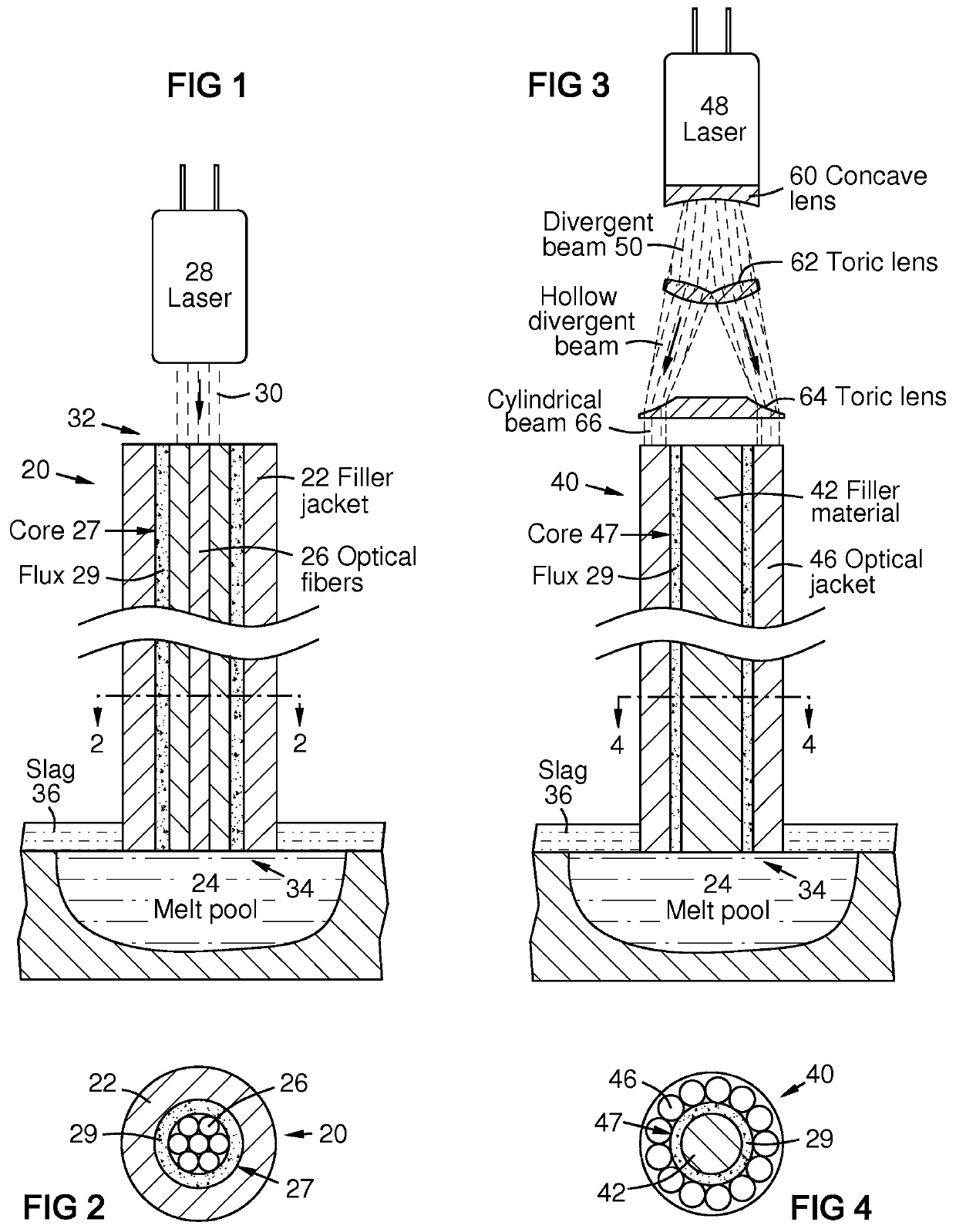
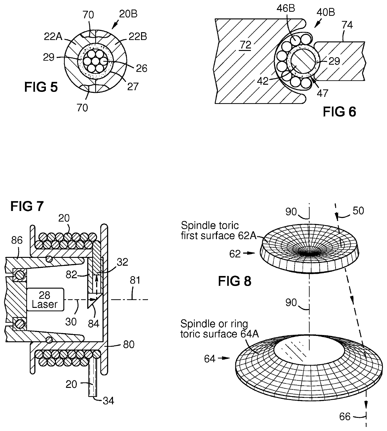
[0020]FIG. 3 is a side sectional view of a filler feed wire embodiment 40 with a core 47 containing filler material 42 and optionally further containing flux 29 and / or additional filler constituents. A laser conductive element, such as optical fibers 46, surrounds the core. A laser emitter 48 injects a laser beam 50 into the laser conductive element at a proximal end of the feed wire via lenses 60, 62, and 64 that shape the beam 50 into a tubular cylindrical beam 66 for injection into the laser conductive element 46. Flux 29 and elemental additions to the filler material may be disposed in the core.

[0021]A benefit of this embodiment is that it can be easily manufactured by coating a filler material wire 42 with flux 29 in a binder such as a polymer, then applying a circular array of optical fibers 46 in a matrix as a jacket on the core 47. The optical fibers 46 may be parallel. Alternately they may be hollow-braided around the core 47 with a braiding machine, then impregnated with a...

embodiment 90

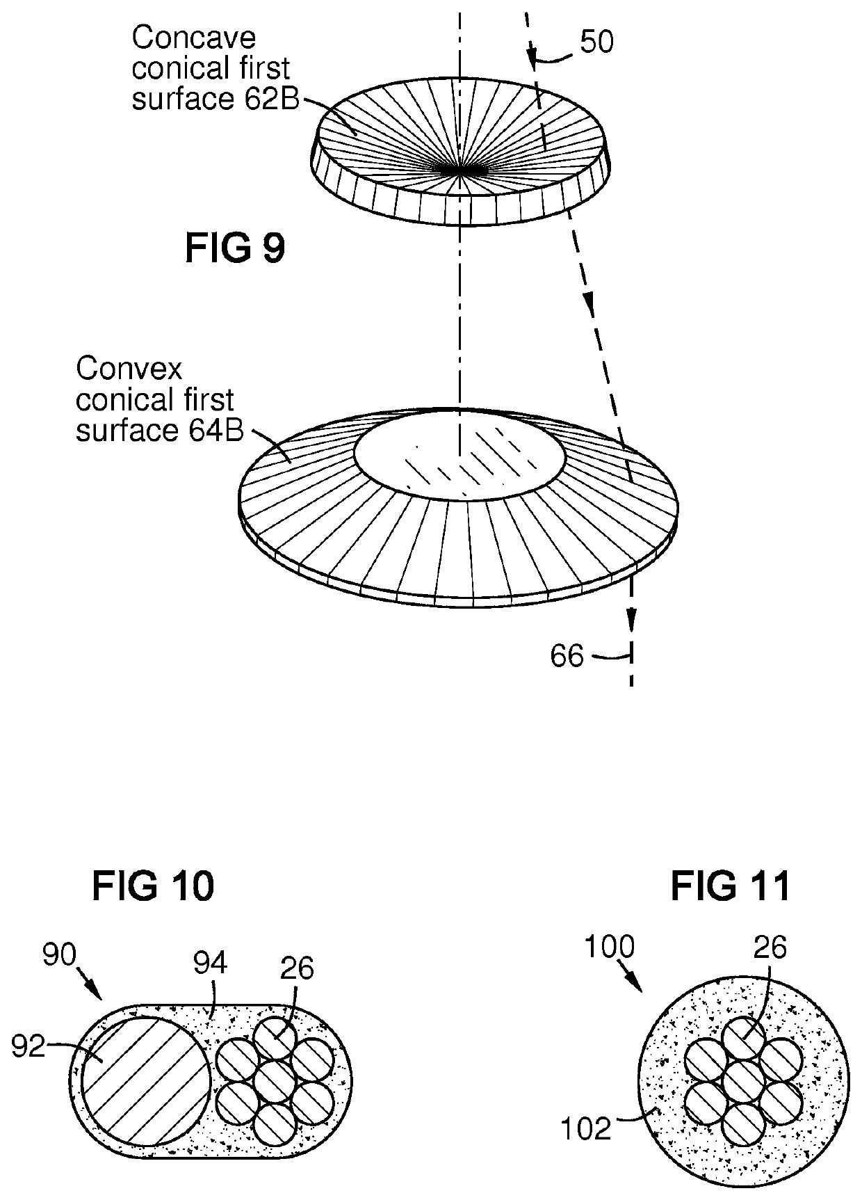
[0028]FIG. 10 is a sectional view of an embodiment 90 having a filler material 92 and an optical conductor 26, bound side-by-side by a binder 94 such as a polymer.

embodiment 100

[0029]FIG. 11 is a sectional view of an embodiment 100 having an optical conductor 26 jacketed by a powdered filler material in a binder 102 such as a polymer containing a concentrated powder of filler and flux constituents.


PUM

PropertyMeasurementUnit
lengthaaaaaaaaaa
conductiveaaaaaaaaaa
gravityaaaaaaaaaa

Abstract

A filler feed wire (20) including both a laser conductive element (26) and a filler material (22) extending along a length of the wire. Laser energy (30) can be directed into a proximal end (32) of the laser conductive element for melting a distal end (34) of the feed wire to form a melt pool (24) for additive fabrication or repair. The laser conductive element may serve as a flux material. In this manner, laser energy is delivered precisely to the distal end of the feed wire, eliminating the need to separately coordinate laser beam motion with feed wire motion.

Description

FIELD OF THE INVENTION[0001]This invention relates to apparatus and methods for additive fabrication and repair, and particularly relates to delivery of laser energy for melting a filler feed wire in such methods.BACKGROUND OF THE INVENTION[0002]Coordinating the delivery of laser energy with feeding of filler material during laser welding and cladding is challenging. Powdered filler may be preplaced, but this is labor intensive, is limited to positioning that can be retained by gravity, and is prone to scattering during processing. A filler feed wire may be fed to any position, but its movement must be coordinated with movement of the laser beam.BRIEF DESCRIPTION OF THE DRAWINGS[0003]The invention is explained in the following description in view of the drawings that show:[0004]FIG. 1 is a side sectional view of a filler feed wire with central laser optical fibers.[0005]FIG. 2 is a transverse sectional view of the filler feed wire of FIG. 1 taken along line 2-2.[0006]FIG. 3 is a sid...

Claims


Application Information

Patent Timeline
Patent Type & Authority Patents(United States)
IPC IPC(8): B23K35/02B23K26/70B23K35/30B23K35/365B23K35/368B23K26/06B23K26/34B23K26/354B23K26/073B22F12/00B33Y10/00B33Y30/00B33Y70/00B22F10/10
CPCB23K35/0261B22F12/00B23K26/0648B23K26/0652B23K26/0734B23K26/34B23K26/354B23K26/702B23K35/0272B23K35/0277B23K35/3033B23K35/365B23K35/368B22F10/10B33Y10/00B33Y30/00B33Y70/00B23K26/342B23K26/70B23K35/00B23P6/00B22F12/44B22F10/25B22F12/41Y02P10/25
Inventor BRUCK, GERALD J.KAMEL, AHMED
Owner SIEMENS ENERGY INC
Why Eureka
Try Eureka