Distance dominant intraocular lens

a technology of intraocular lenses and distance, applied in intraocular lenses, instruments, spectales/goggles, etc., can solve the problems of loss of such accommodation for supporting a range of focusing options, and achieve the effects of reducing energy devoted, minimizing unwanted visual effects, and increasing distance energy

Active Publication Date: 2022-05-31
BAUSCH & LOMB INC
View PDF10 Cites 0 Cited by
  • Summary
  • Abstract
  • Description
  • Claims
  • Application Information

AI Technical Summary

Benefits of technology

[0004]According to an aspect of the present disclosure, a tri-focal IOL is envisioned with a distance vision dominant energy distribution under low light conditions while still providing good near and intermediate vision under bright light conditions. Diffractive profiles supporting near and intermediate vision can be apodized as a function of radial distance so that as the user's pupil opens under mesopic conditions, the proportion of light directed into the optical powers supporting near and intermediate vision is reduced leaving more light directed through the optical power supporting distance vision. This increase in distance energy with reduced near / intermediate energy under mesopic conditions is expected to minimize unwanted visual effects. The increased distribution of light supporting distance vision with pupil enlargement can be drawn primarily from a reduction in the energy devoted to near vision so that the energy devoted to intermediate vision provides a transition zone between distance and near vision over the considered range of pupil enlargement.
[0006]The diffractive profiles can be formed by superimposing different diffractive patterns for supporting near and intermediate vision through first and second orders of diffraction while preserving distance vision through the zero diffractive order. First order diffraction through a finer pitch diffractive pattern supports the increased focusing power of near vision, and first order diffraction through a coarser pitch diffractive pattern supports the lesser focusing power of intermediate vision. However, instead of harmonically relating the two diffractive patterns so that the features of the two patterns periodically overlap, the progressive periodicities of the two patterns depart from such regularity so that the optical power contributed by the second order of the coarser pitch pattern departs slightly from the optical power contributed by the first order of the finer pitch diffractive pattern to extend the depth of focus associated with near vision. Thus, instead of using the second order of the coarser pitch diffractive pattern to contribute to the near power otherwise provided by the finer pitch diffractive pattern, the second order of the coarser pitch diffractive pattern increases the depth of focus associated with the near power.
[0012]An intraocular lens in accordance with this disclosure can also be described as having a base refractive structure with anterior and posterior surfaces that are shaped for producing a first optical power that directs incident light through a distance focus and a diffractive structure formed in one of the surfaces of the base refractive structure over a common aperture for producing second and third optical powers that in combination with the first optical power direct incident light through respective intermediate and near foci. The diffractive structure includes a first diffractive pattern for producing the second optical power through a first order diffraction and a second diffractive pattern for producing the third optical power through a first order diffraction. The first and second diffraction patterns are superimposed over the common aperture and have non-harmonic periodicities so that a second order diffraction through the first diffractive pattern extends the focal depth of the near focus.

Problems solved by technology

Replacement of the crystalline lenses with manufactured intraocular lenses (IOLs), such as during cataract surgery, has long resulted in a loss of such accommodation for supporting a range of focusing options.

Method used


Image

  • Distance dominant intraocular lens
  • Distance dominant intraocular lens
  • Distance dominant intraocular lens

Examples


Embodiment Construction

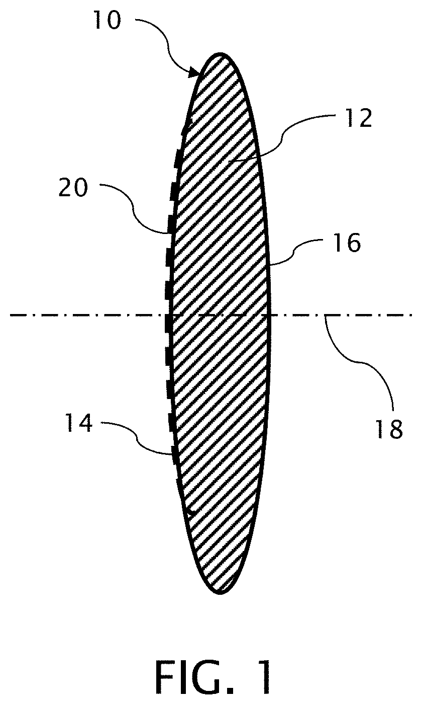
[0028]An intraocular lens (IOL) 10 shown in FIG. 1 has a base refractive structure 12 in a generalized form of a lens including a convex anterior surface 14 and a convex posterior surface 16 but is intended to be representative of IOLs of a variety of known forms including refractive structures with various combinations of concave, convex and planar surfaces. In addition, while the anterior and posterior surfaces 14 and 16 appear as spherical surfaces, both surfaces 14 and 16 are preferably aspheric surfaces centered about a common optical axis 18. A diffractive structure 20, which is intended to be constructed in accordance with various embodiments of this disclosure, is superimposed on the anterior surface 14 of the IOL 10 and is incorporated into the shape of the anterior surface 14.

[0029]Both the refractive profile contributed by the base refractive structure 12 and the diffractive profile contributed by the diffractive structure 20 in the anterior surface 14 are axially symmetr...


PUM


Abstract

An intraocular lens includes a base refractive structure having anterior and posterior surfaces that are shaped for producing a first optical power and a diffractive structure formed in one of the surfaces of the base refractive structure including overlapping first and second diffractive patterns over a common aperture for producing second and third optical powers. The second optical power is an uneven division of the third optical power. The first and second diffractive patterns have respective step heights that are separately varied as a function of radial distance from the optical axis over the common aperture.

Description

TECHNICAL FIELD[0001]This invention generally relates to multi-focal intraocular lenses and particularly such lenses with compound diffraction gratings on refractive bases with aspheric surfaces.BACKGROUND OF THE INVENTION[0002]Natural crystalline lenses in the human eye accommodate power variations required to support a range of focal distances from near to far (distance) vision by changing shape. Replacement of the crystalline lenses with manufactured intraocular lenses (IOLs), such as during cataract surgery, has long resulted in a loss of such accommodation for supporting a range of focusing options. Monocular IOLs require patients to choose a given focal power, such as for supporting near or far vision, and to use eyeglasses to focus at some other distance.[0003]Multi-focal IOLs are typically designed to provide two or more annular zones that provide different optical powers, typically using refractive and / or diffractive focusing mechanisms. Each of the annular zones has a diff...

Claims


Application Information

Patent Timeline
Patent Type & Authority Patents(United States)
IPC IPC(8): A61F2/16G02C7/06G02C7/04
CPCA61F2/1618A61F2/1654G02C7/041G02C7/06G02C2202/20
Inventor TIWARI, NIVEDANVENKATESWARAN, KRISHNAKUMARJONES, ANDREW WILLIAMZHAN, CHUNSALVATORI, LORENZO
Owner BAUSCH & LOMB INC
Why Eureka
Try Eureka