
Heat exchanger module

a heat exchanger and module technology, applied in indirect heat exchangers, lighting and heating apparatus, instruments, etc., can solve the problems of limited heat dissipation effect of single parallel-flow heat exchangers, affecting the working stability of equipment, and increasing the heat generated by internal equipment of cabinets in multiples, so as to achieve further improved heat dissipation efficiency and air flow temperature drop

Active Publication Date: 2022-05-24
SHENZHEN ENVICOOL TECH
View PDF16 Cites 0 Cited by
  • Summary
  • Abstract
  • Description
  • Claims
  • Application Information

AI Technical Summary

Benefits of technology

The invention provides a heat exchanger module with good heat dissipation effect using a counter-current mounting method in the parallel-flow heat exchanger. The coolant temperatures of the heat exchangers gradually decrease along the air flow direction, resulting in a better heat exchange effect and improved heat transfer efficiency. The technical effects of this method include a simplified structure of the heat exchanger module and improved heat dissipation efficiency.

Problems solved by technology

With the original size unchanged, the heat generated by the internal equipment of the cabinet increases in multiples, and the increased internal temperature of the cabinet affects the working stability of the equipment.
But the heat dissipation effect of the single parallel-flow heat exchanger is limited, and the heat transfer ability of the single parallel-flow heat exchanger is not enough to meet the heat dissipation requirement of the cabinet.

Method used


Image

  • Heat exchanger module
  • Heat exchanger module

Examples


embodiment 1

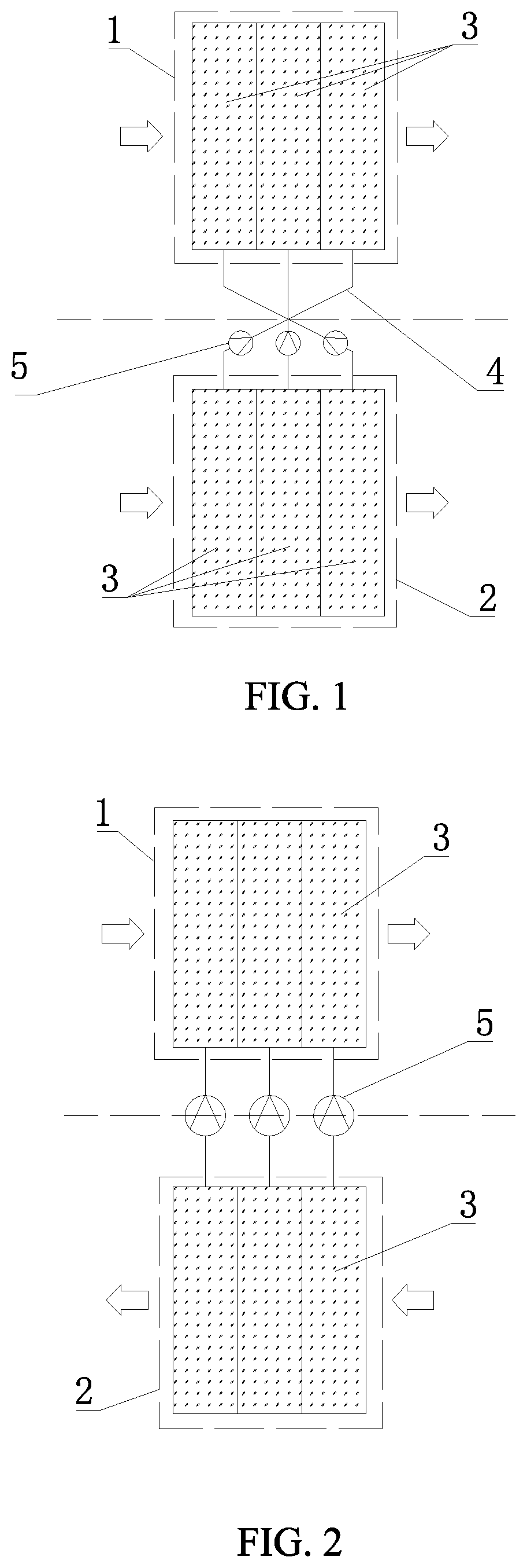
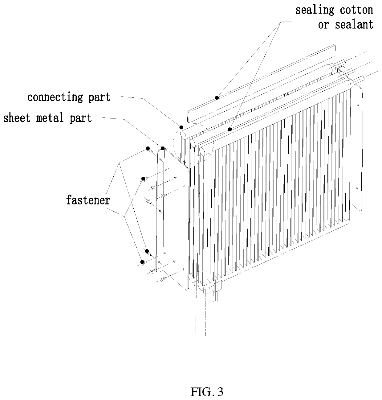
[0023]As shown in FIG. 1, the heat exchanger module of this embodiment includes a condenser unit 1 that performs heat exchange with the outdoor air flow and an evaporator unit 2 that performs heat exchange with the indoor air flow, for example, the condenser unit can be disposed outside the cabinet (or outdoors), and the evaporator unit may be disposed inside the cabinet (or indoors). The condenser unit 1 includes N pieces of parallel-flow heat exchangers, wherein N≥2. In the embodiment, the condenser unit 1 includes 3 pieces of parallel-flow heat exchangers 3, and the parallel-flow heat exchangers 3 are arranged adjacently, the parallel-flow heat exchangers of the embodiment are connected integrally by screws or rivets, and sealing cotton or sealant acting as a seal is arranged at the connecting part of the adjacent parallel-flow heat exchangers 3, so as to prevent the gaps between adjacent parallel-flow heat exchangers 3 from leaking and affecting the heat transfer. The evaporator...

embodiment 2

[0026]As shown in FIG. 2, the difference between the present embodiment and the embodiment 1 is that the pipes connecting the parallel-flow heat exchangers in the condenser unit 1 and the parallel-flow heat exchangers in the evaporator unit 2 in the present embodiment are correspondingly connected, the air flow outside the cabinet is also subjected to heat exchange through three parallel-flow heat exchangers with gradually increasing refrigerant temperature in sequence, and the air flow inside the cabinet is subjected to heat exchange through three parallel-flow heat exchangers with gradually decreasing refrigerant temperature in sequence, so that sufficient heat exchange of the heat exchanger is ensured, and the space in the cabinet can be fully utilized, no longer limited by the height and width, so that the heat exchange design is miniaturized and convenient.

[0027]The number of the parallel-flow heat exchangers in the condenser unit and the evaporator unit of the present inventio...


PUM


Abstract

A heat exchanger module includes a condenser unit and an evaporator unit. The evaporator unit includes N pieces of parallel-flow heat exchangers arranged adjacently, and the coolant temperatures reduce gradually from the first to Nth parallel-flow heat exchangers along an air flow direction in the evaporator unit. A counter-current mounting method is adopted in the parallel-flow heat exchangers of the evaporator unit in the heat exchanger module provided by the present invention. The coolant temperature of each parallel-flow heat exchanger is lower than that of the previous one, the temperature difference between air and coolant is relatively uniform by using the counter-current method so as to reach a better heat exchange effect.

Description

CROSS REFERENCE TO RELATED APPLICATIONS[0001]This application is the national phase entry of International Application PCT / CN2017 / 087621, filed on Jun. 8, 2017, which is based upon and claims priority to Chinese Patent Application No. 201620569983.5, filed on Jun. 13, 2016, the entire contents of which are incorporated herein by reference.TECHNICAL FIELD[0002]The present invention relates to a heat exchanger module, in particular to a heat exchanger module used in a data center cabinet.BACKGROUND[0003]With the development of technology, the heat generated by communication equipment is getting higher and higher. With the original size unchanged, the heat generated by the internal equipment of the cabinet increases in multiples, and the increased internal temperature of the cabinet affects the working stability of the equipment. As a result, on the premise of not changing the size of the equipment cabinet, there is an urgent need for a radiator, which is small in size, large in refrig...

Claims


Application Information

Patent Timeline
Patent Type & Authority Patents(United States)
IPC IPC(8): F28D15/02H05K7/20G06F1/20F25B39/00F25B23/00F25B39/02F25B39/04
CPCF28D15/0275F25B23/006F25B39/00F25B39/028F25B39/04G06F1/20H05K7/20663H05K7/20681F28D2015/0216G06F2200/201
Inventor CAO, WENQIANGZENG, QINGZHENLIU, JUN
Owner SHENZHEN ENVICOOL TECH
Learn More