Communication system

a communication system and communication system technology, applied in the field of communication systems, can solve the problems of inability to successfully receive all pucch data near the edge of the system bandwidth, inability to reuse existing (lte-specific) design in 5g nr systems, and inability to achieve the effect of ensuring efficiency and flexibility

Active Publication Date: 2022-05-10
NEC CORP
View PDF1 Cites 1 Cited by
  • Summary
  • Abstract
  • Description
  • Claims
  • Application Information

AI Technical Summary

Benefits of technology

[0014]Accordingly, preferred example embodiments of the present invention aim to provide alternative methods and apparatus which may be used to address the above issues whilst ensuring efficiency and flexibility, and that allow the UE to determine the particular PUCCH resource that the UE is expected to use.

Problems solved by technology

However, this existing (LTE-specific) design cannot be easily reused in 5G NR systems because different UEs (e.g. MTC devices) designed for different application scenarios may be equipped with transceivers supporting different operating bandwidths, which operating bandwidth may in some cases be smaller than the system bandwidth.
Accordingly, whilst most UEs are expected to support simultaneous reception over the entire system bandwidth (which may be up to 1 GHz in NR), some UEs (such as MTC devices) with a relatively limited bandwidth (compared to the system bandwidth in a given cell) would be unable to successfully receive all the PUCCH data sent near the edges of the system bandwidth.
However, allocation of a PUCCH region near the edges of the radio frequency bandwidth supported by the UEs (as opposed to a PUCCH region near the edges of the system bandwidth) may potentially result in a fragmented utilization of the frequency spectrum available to the base station and disrupt contiguous uplink transmissions (since the PUCCH region for some UEs would need to be provided at a location other than near the edges of the system bandwidth, resulting in a fragmentation of the portion of the system bandwidth that may be used for data transmissions).
However, even in this case the channel ‘PUCCH1’ still collides with ‘PUSCH2’, thereby, fragmenting the resources of BWP2.
However, this option is likely to complicate system design and hinder the adoption of a unified solution for PUCCH resource configuration and indication.
Although a number of different explicit and implicit approaches have been proposed to allow UEs to transmit the HARQ-ACK on the allocated PUCCH resource, there is no agreement in 3GPP yet regarding how to address the issue of PUCCH resource allocation in NR when BWP is employed.

Method used


Image

  • Communication system
  • Communication system
  • Communication system

Examples


Embodiment Construction

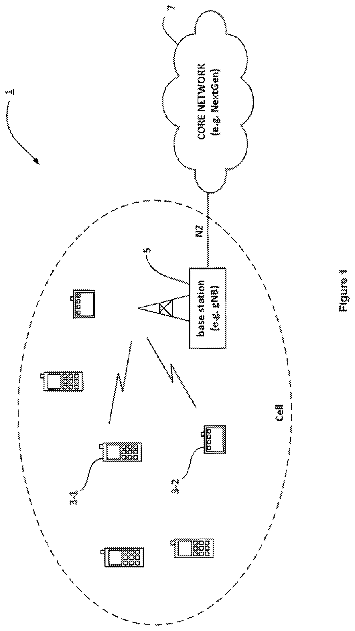
[0027]FIG. 1 schematically illustrates a (cellular) telecommunications network 1 in which user equipment 3 (mobile telephones and / or other mobile devices) can communicate with each other via base stations 5 (e.g. a ‘gNB’ in NR networks) using an appropriate radio access technology (RAT). It will be appreciated that in 5G systems base stations are also referred to as including one or more transmit receive points (TRPs). As those skilled in the art will appreciate, whilst six mobile device 3 and one base station 5 are shown in FIG. 1 for illustration purposes, the system, when implemented, will typically include other base stations and mobile devices.

[0028]Each base station 5 operates one or more associated cells either via a TRP located at the base station (and / or one or more remotely located TRPs). In this example, for simplicity, the base station 5 operates a single cell having an associated system bandwidth. The base station 5 is connected to a core network 7 (e.g. via an appropri...


PUM


Abstract

A communication system is disclosed in which a base station communicates with user equipment via an associated cell having a system bandwidth. The system bandwidth comprises a bandwidth part having a set of contiguous physical resource blocks. The base station initiates a random access procedure with the user equipment; provides first information identifying a set of frequency resources for an uplink channel; and provides second information identifying at least one specific frequency resource, within said set of frequency resources, for said uplink communication. The first information is provided prior to completion of the random access procedure.

Description

CROSS REFERENCE TO RELATED APPLICATIONS[0001]This application is a National Stage of International Application No. PCT / JP2018 / 040396 filed Oct. 30, 2018, claiming priority based on United Kingdom Patent Application No. GB1718999.4 filed Nov. 16, 2017 and GB1800393.9 filed Jan. 10, 2018.TECHNICAL FIELD[0002]The present invention relates to a communication system. The invention has particular but not exclusive relevance to wireless communication systems and devices thereof operating according to the 3rd Generation Partnership Project (3GPP) standards or equivalents or derivatives thereof. The invention has particular although not exclusive relevance to the provision of control channels and resource allocation in the so-called ‘Next Generation’ systems.BACKGROUND ART[0003]The latest developments of the 3GPP standards are referred to as the Long Term Evolution (LTE) of Evolved Packet Core (EPC) network and Evolved UMTS Terrestrial Radio Access Network (E-UTRAN), also commonly referred a...

Claims


Application Information

Patent Timeline
Patent Type & Authority Patents(United States)
IPC IPC(8): H04W4/00H04W72/04H04L1/18H04W74/08
CPCH04W72/0453H04L1/1812H04W72/0413H04W74/0833H04W72/21H04W72/20Y04S20/30
Inventor IJAZ, AYESHAAWAD, YASSIN ADENARNOTT, ROBERT
Owner NEC CORP
Why Eureka
Try Eureka