
System for thermal development of flexographic printing plates

a technology of thermal development and flexographic printing, which is applied in the field of system and method for forming reliefs, can solve the problems of user exposure to irritants of photopolymer material during filter removal, environment and user, and achieve the effect of eliminating the potential for user or environmental contact and easy and safe disposal

Active Publication Date: 2022-05-10
MACDERMID PRINTING SOLUTIONS
View PDF20 Cites 0 Cited by
  • Summary
  • Abstract
  • Description
  • Claims
  • Application Information

AI Technical Summary

Benefits of technology

The system effectively reduces or eliminates the reactivity of byproducts, allowing for safe disposal and minimizing environmental and user exposure to harmful contaminants.

Problems solved by technology

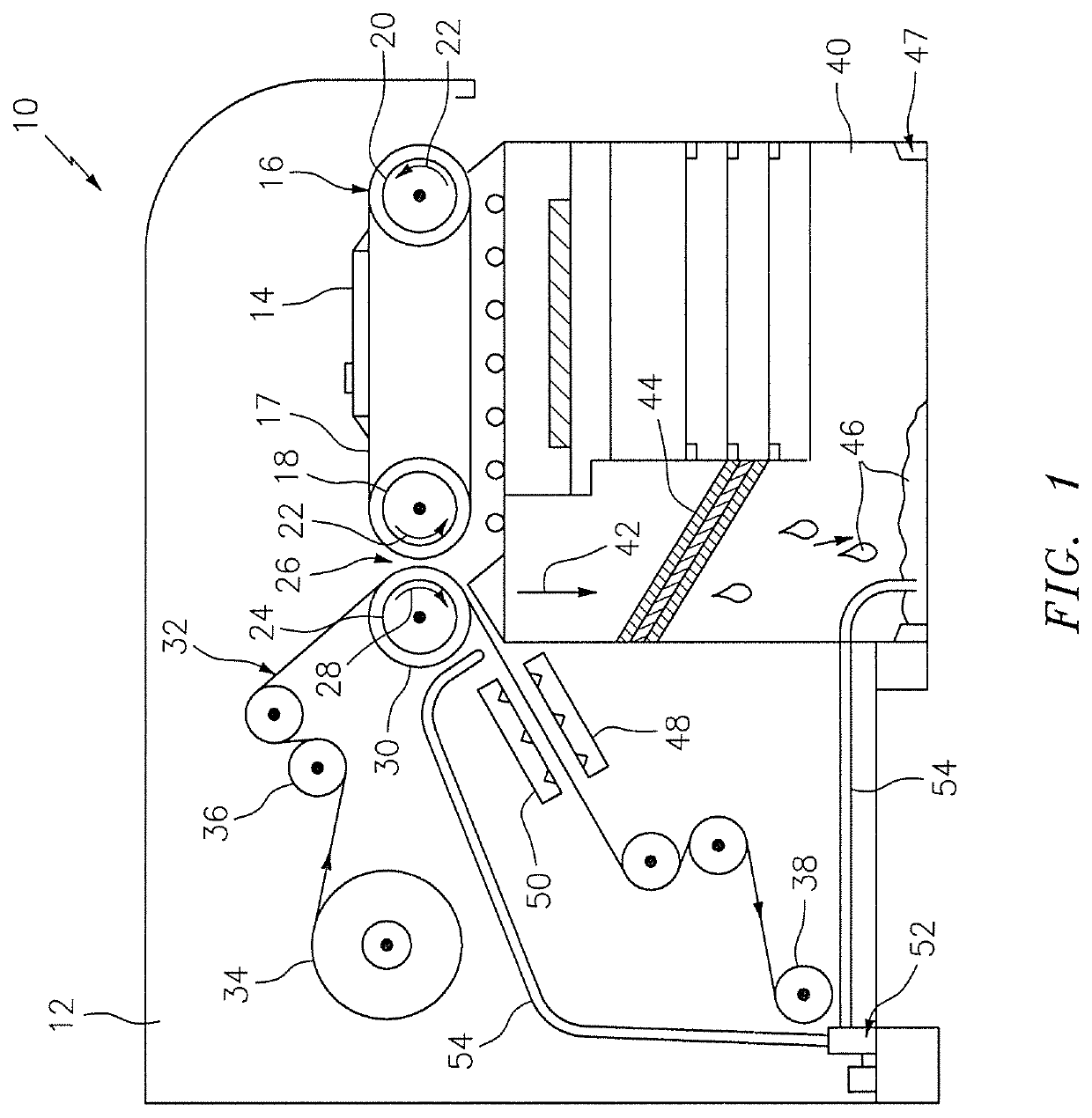
A disadvantage of the disclosed ventilation system is that the volatile organic compounds and other contaminants captured by the filtering system, although removed from the enclosure, remain liquid and thus are reactive, thereby potentially exposing a user to the irritants of photopolymer material during filter removal / cleaning.
The vapors may also contain contaminants and irritants of photopolymer material that may be harmful to the environment and the user.

Method used


Image

  • System for thermal development of flexographic printing plates
  • System for thermal development of flexographic printing plates
  • System for thermal development of flexographic printing plates

Examples


example 1

[0083]A liquid condensate produced in a thermal developing assembly was applied to two side-by-side locations on a surface of an absorbent material of a LAVA® 4260 platemaking machine (produced by MacDermid Graphics Solutions, Atlanta, Ga.). Each location of the absorbent material contained a representative amount of liquid condensate that is consistent with the quantity of liquid condensate generated on each pass of the LAVA® machine.

[0084]The first location on the absorbent material with the liquid condensate was exposed to UV light of 365 nm wavelength with a maximum intensity of approximately 14.3 to 14.55 mW / cm2 (measured 10 mm from the front window of the light source).

[0085]The second location on the absorbent material with the liquid condensate was left untouched and not exposed to UV light. The absorbent material was traveling at 3 ft / min.

[0086]The UV light source had a total lamp power of 20 watts, resulting in 8 watts at 365 nm UV after conversion losses.

[0087]As illustra...


PUM

PropertyMeasurementUnit
wavelength rangeaaaaaaaaaa
temperatureaaaaaaaaaa

Abstract

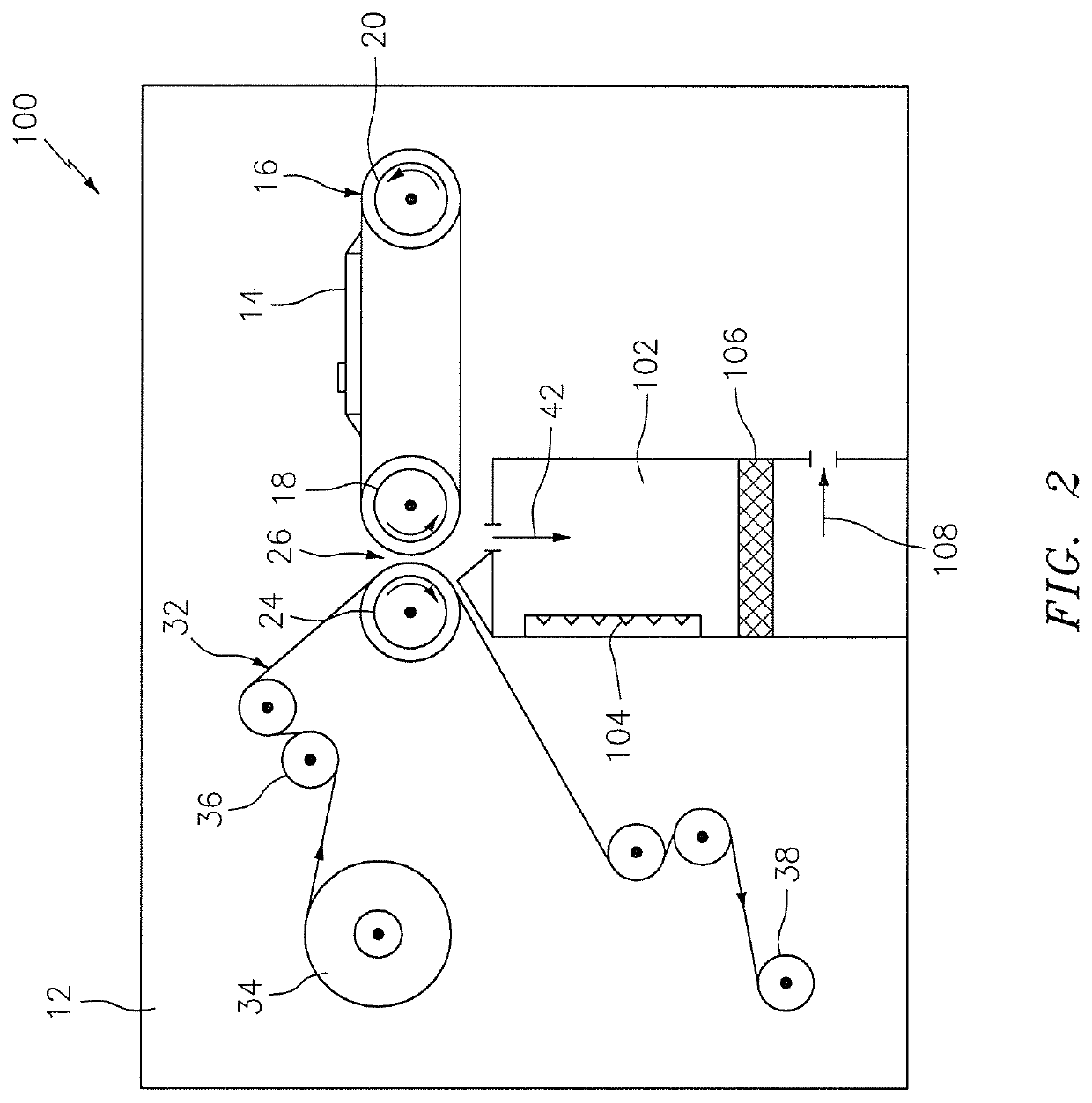
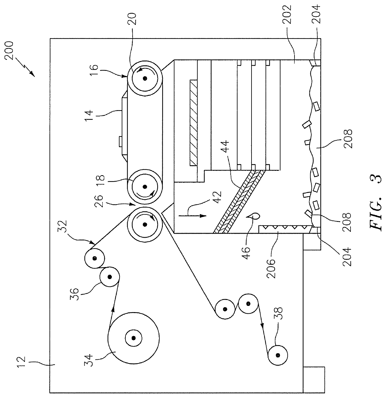
The present disclosure is directed to a thermal developing assembly that is configured to reduce (or eliminate) the reactivity of contaminants and / or unreacted photosensitive material associated with forming a relief image on a photosensitive printing element during thermal development. The thermal developing assembly is configured to reduce (or eliminate) the reactivity of a byproduct associated with forming a relief image on a photosensitive printing element, the byproduct including but not limited to, contaminants within vapors (e.g., fumes), contaminants within condensate, unreacted photosensitive material, and combinations thereof.

Description

FIELD OF THE INVENTION[0001]The present disclosure generally relates to a system and method for forming a relief structure suitable for flexographic printing and, more generally, a system and method configured to reduce (or eliminate) the reactivity of vapor and / or liquid byproducts associated with forming a relief image on a photosensitive printing element in a thermal developing assembly.BACKGROUND OF THE INVENTION[0002]Flexography is a method of printing that is commonly used for high-volume runs. Flexography is employed for printing on a variety of substrates such as paper, paperboard stock, corrugated board, films, foils and laminates. Newspapers and grocery bags are prominent examples. Coarse surfaces and stretch films can be economically printed only by means of flexography. Flexographic printing plates are relief plates with image elements raised above open areas. Such plates offer a number of advantages to the printer, based chiefly on their durability and the ease with whi...

Claims


Application Information

Patent Timeline
Patent Type & Authority Patents(United States)
IPC IPC(8): B41C1/055G03F7/36
CPCB41C1/055G03F7/36G03F7/3092
Inventor MARKHART, GARY T.VEST, RYAN W.
Owner MACDERMID PRINTING SOLUTIONS
Learn More