Sink assembly

a technology of sink and assembly, which is applied in the direction of domestic plumbing, sedimentation settling tanks, construction, etc., can solve the problems of contaminated liquids being allowed to drain away, particulate contaminants no longer trapped, and difficulty in cleaning out the catchment area, etc., to facilitate safe and easy disposal of particulate contaminants

Active Publication Date: 2017-12-05
SMART SINKS
View PDF7 Cites 0 Cited by
  • Summary
  • Abstract
  • Description
  • Claims
  • Application Information

AI Technical Summary

Benefits of technology

[0007]It is one object of the present invention to provide a particulate trapping and drainage system that facilitates safe and easy disposal of particulate contaminants trapped thereby.
[0008]It is another object of the present invention to provide a particulate catching drainage sink system that has multiple cascaded levels of contaminant trapping, such that the failure of one level does not immediately result in a total failure of the system to trap and contain the contaminants.
[0009]It is a further object of the present invention to provide a particulate catching drainage sink system that automatically prevents contaminated liquids from draining away when a predetermined number of levels of contaminant trapping have failed.

Problems solved by technology

One disadvantage of conventional drainage sink systems, however, is the difficulty and complexity involved in cleaning out the catchment area.
A further disadvantage of conventional drainage sink systems is that after the catchment area is full, particulate contaminants are no longer trapped in the catchment area.
Consequently, further input of particulate contaminated liquids into conventional drainage sink systems results in the contaminated liquids being allowed to drain away with particulate contaminants still suspended therein.

Method used


Image

  • Sink assembly
  • Sink assembly
  • Sink assembly

Examples


Embodiment Construction

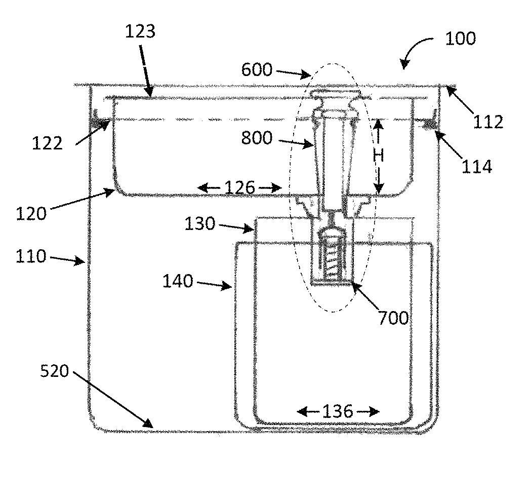
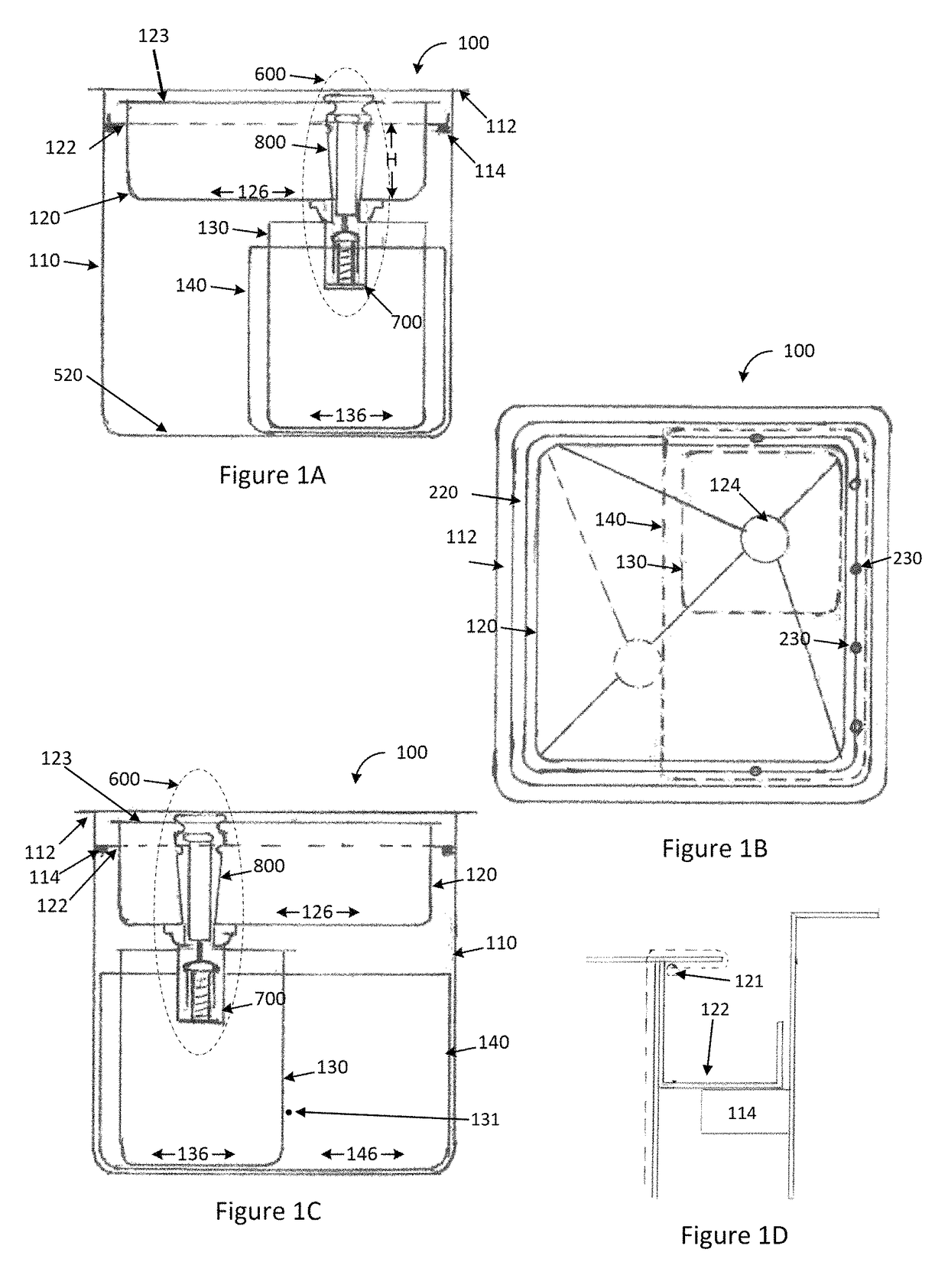
[0063]FIG. 1 illustrates a trapping and drainage system 100 according to a preferred embodiment of the present invention. The system 100 is designed to facilitate the separation of particulate contaminants from a liquid, and to subsequently allow the substantially contaminant-free liquid to drain away.

[0064]The trapping and drainage system 100 comprises a master trap 110, within which are removably situated a first trap 120, a second trap 130, and a third trap 140. The master trap 110, in a preferred form, is installed into a workbench in a top-mounted arrangement, where a lip 112 of the master trap 110 rests on top of a surface of the workbench. In other forms, the master trap 100 may be integrated with the bench, top-mounted with a sunken configuration, bottom-mounted with respect to a workbench, or be configured as a stand-alone mobile unit.

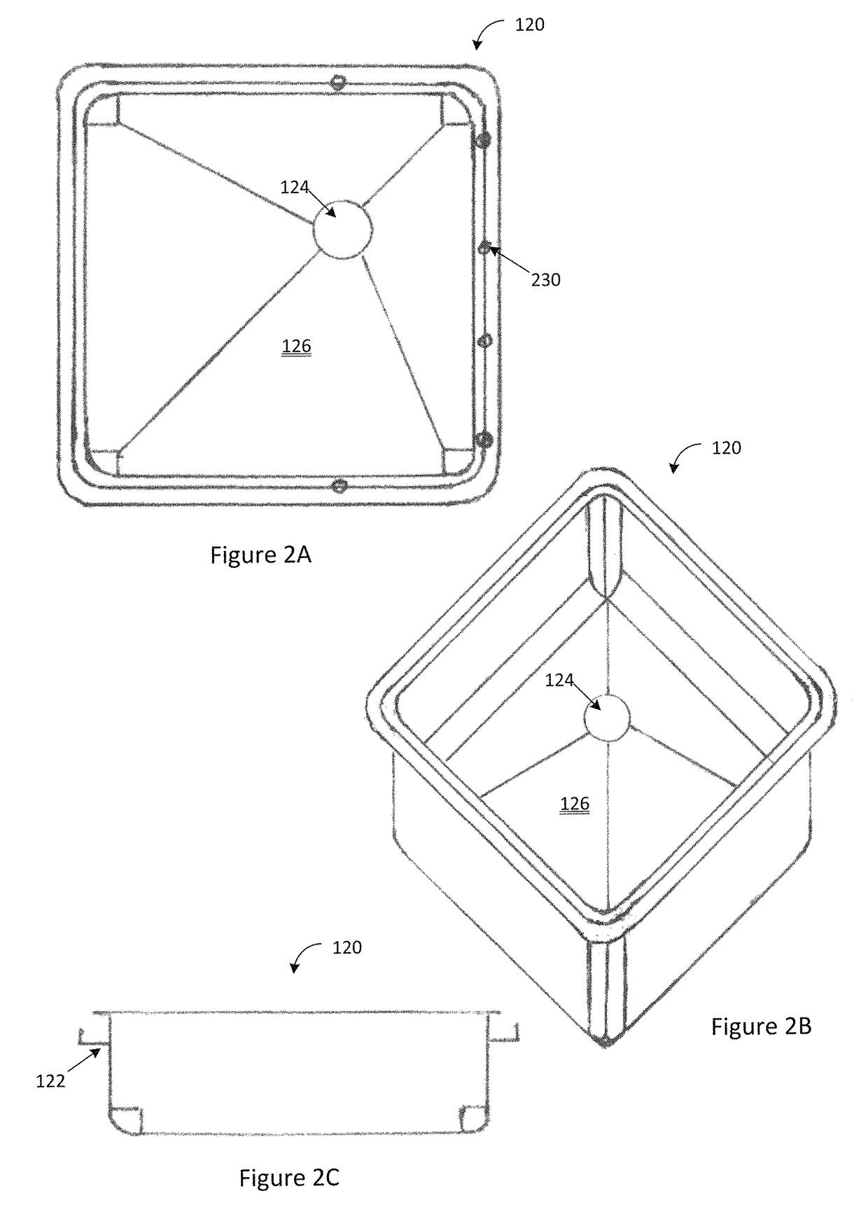
[0065]The first trap 120 is situated near a top of the master trap 110, and supported by the master trap 110 via a ledge or other protrusion ...


PUM

PropertyMeasurementUnit
heightaaaaaaaaaa
areaaaaaaaaaaa
volumeaaaaaaaaaa

Abstract

The present invention is directed to a sink assembly that can separate particulate contaminants from a liquid in which they are suspended. The sink assembly includes a master trap and at least a first trap with a riser and valve assembly to collect particulates and prevent overflow from the master trap. The sink assembly provides a simple maintenance and cleaning solution.

Description

FIELD OF INVENTION[0001]The present invention relates to particulate trapping and drainage systems. The present invention has particular but not exclusive application with sinks used to trap and drain particulate contaminated liquids.BACKGROUND OF THE INVENTION[0002]Operations and processes such as those used in dental laboratories, painting, drilling, cutting, and the like produce waste products in the form of particulate contaminated liquid. The particulate contaminated liquid resultant from such processes contains a mixture of particulate matter suspended in the liquid. Proper disposal of particulate contaminated liquids dictates that the particulate contaminates should first be trapped before permitting the liquid permitted to drain away.[0003]To facilitate the proper disposal of such particulate contaminated liquids, trapping and drainage sink systems have been developed. Conventional trapping and drainage sink systems allow particulate contaminants to settle out of the liquid ...

Claims


Application Information

Patent Timeline
Patent Type & Authority Patents(United States)
IPC IPC(8): E03C1/232E03C1/242E03C1/18B01D21/30B01D21/34B01D21/02
CPCE03C1/242B01D21/307E03C1/18B01D21/34B01D21/02
Inventor HANSON, CRAIG
Owner SMART SINKS
Why Eureka
Try Eureka