Seamless hinge and electronic device having the same

Active Publication Date: 2022-05-03
COMPAL ELECTRONICS INC
View PDF22 Cites 5 Cited by
  • Summary
  • Abstract
  • Description
  • Claims
  • Application Information

AI Technical Summary

Benefits of technology

The patent describes a seamless hinge for electronic devices that allows for a more aesthetically pleasing appearance and smaller size. The hinge is pivotally rotated along a virtual axis when applied to the device, reducing the gap when opened and allowing for a seamless connection between parts. A carrying frame is used to slide along two fixing assemblies and drive the shaft, reducing the swinging range of the frame. Multiple hinges are used to connect the parts of the device, allowing for a more seamless connection and a smaller gap between parts when opened. Overall, the seamless hinge provides a more polished appearance and a more compact size for electronic devices.

Problems solved by technology

In addition, the carrying frame can only slide relative to the two fixing frames within an angular range, thereby limiting the pivoting angle of the carrying frame.

Method used


Image

  • Seamless hinge and electronic device having the same
  • Seamless hinge and electronic device having the same
  • Seamless hinge and electronic device having the same

Examples


Embodiment Construction

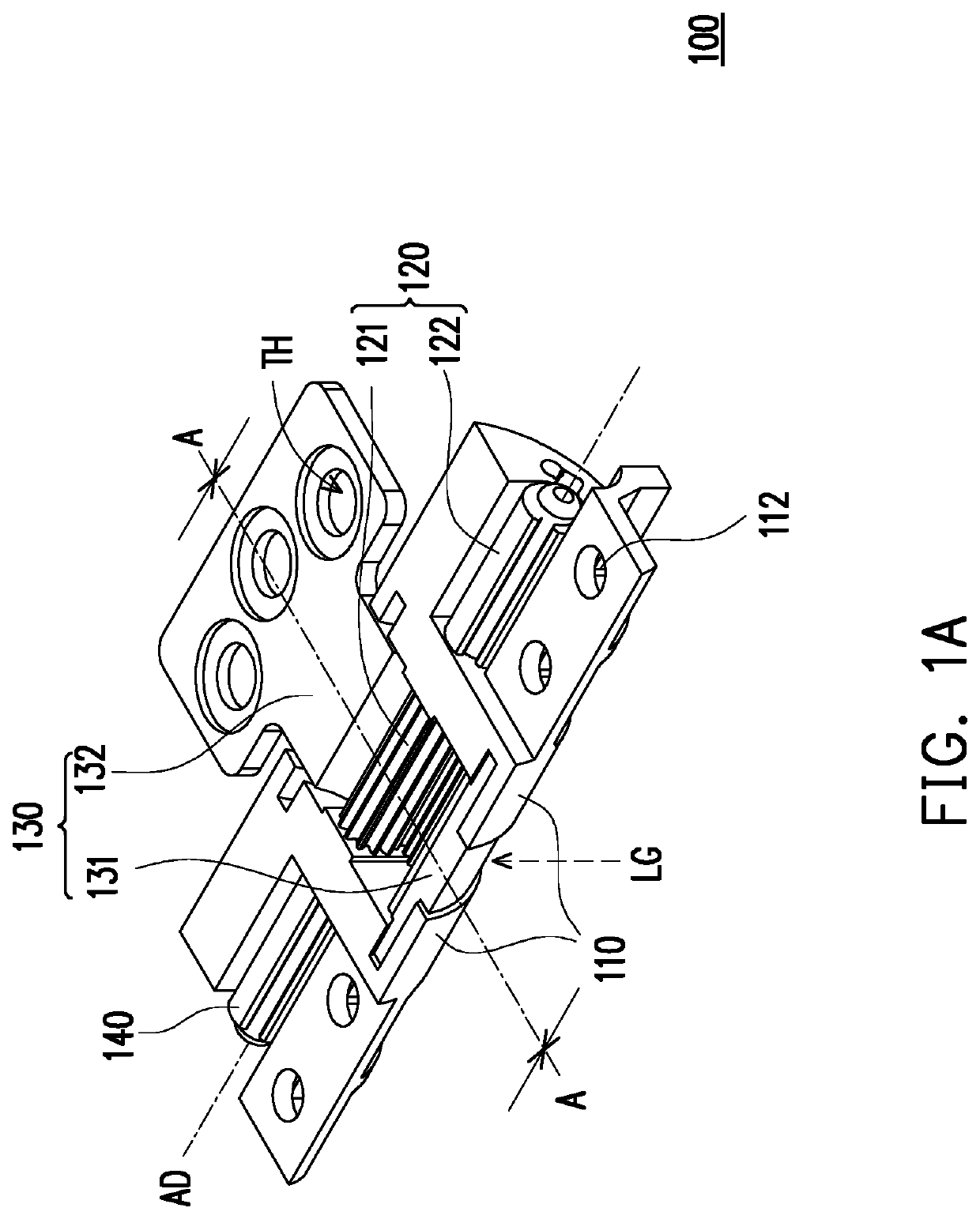
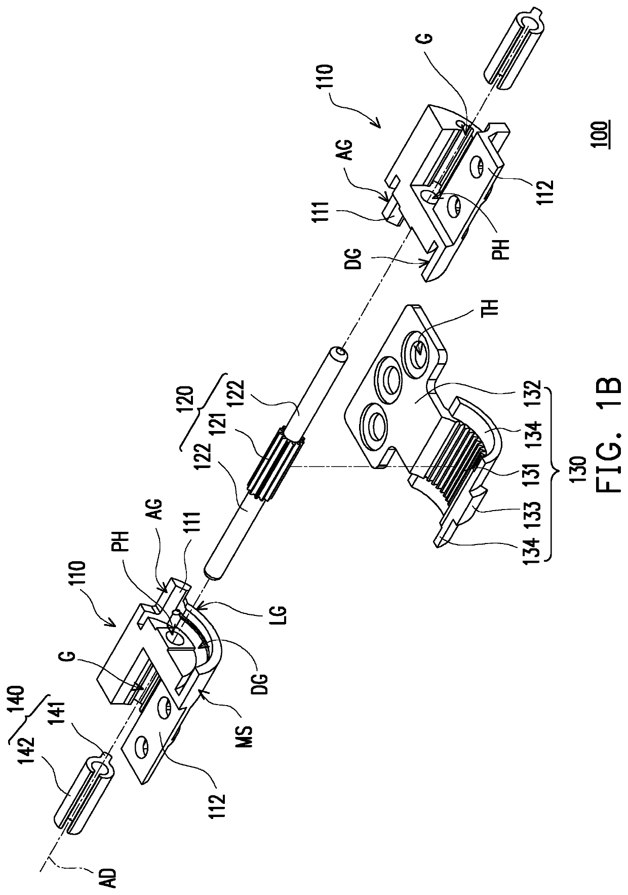
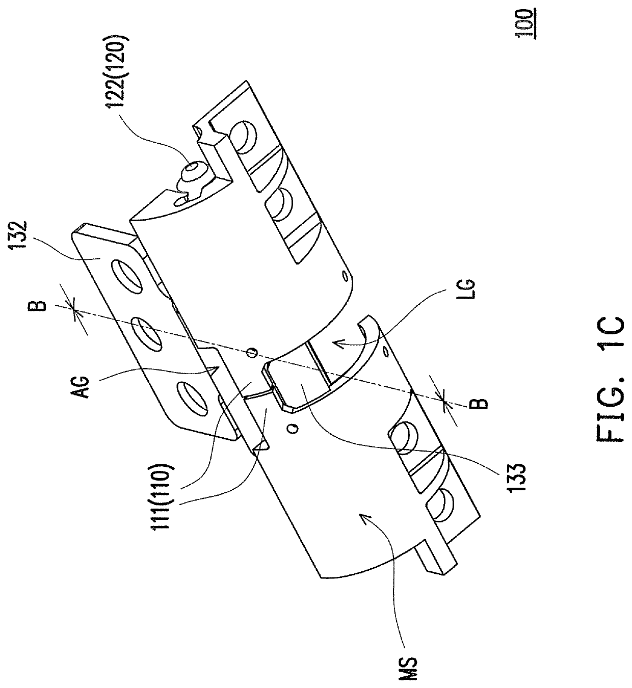
[0025]FIG. 1A is a three-dimensional schematic view of a seamless hinge according to an embodiment of the disclosure. FIG. 1B is another three-dimensional schematic view of the seamless hinge of FIG. 1A. FIG. 1C is an exploded schematic view of the elements of the seamless hinge of FIG. 1A. FIG. 1D is a schematic cross-sectional view of the seamless hinge of FIG. 1A taken along line A-A. FIG. 1E is a schematic cross-sectional view of the seamless hinge of FIG. 1B taken along line B-B.

[0026]FIG. 1F is a schematic cross-sectional view of the seamless hinge of FIG. 1A taken along line A-A in another direction. FIG. 1G is a schematic cross-sectional view of the seamless hinge of FIG. 1B taken along line B-B in another direction.

[0027]Referring to FIG. 1A to FIG. 1C, the seamless hinge 100 of the embodiment includes two fixing frames 110, a shaft 120, a carrying frame 130, and two torsion members 140.

[0028]The two fixing frames 110 are spaced apart from each other and are located on the ...


PUM


Abstract

A seamless hinge including two fixing frames, a shaft, and a carrying frame. The shaft is pivotally connected to the two fixing frames and has a gear portion located between the two fixing frames. The carrying frame is slidably disposed in the two fixing frames and has a rack portion engaged with the gear portion. The carrying frame is adapted to slide in an angular range relative to the two fixing frames and the shaft is driven by the rack portion, so that the carrying frame is pivotally rotated along a virtual axis.

Description

CROSS-REFERENCE TO RELATED APPLICATION[0001]This application claims the priority benefit of U.S. provisional application Ser. No. 62 / 851,083, filed on May 21, 2019. The entirety of the above-mentioned patent application is hereby incorporated by reference herein and made a part of this specification.BACKGROUNDField of the Disclosure[0002]The disclosure relates to a hinge, and particularly to a seamless hinge applied to an electronic device and rotating along a virtual axis.Description of Related Art[0003]Existing notebook computers include a display screen, a host, and a hinge module. The display screen and the host are pivotally connected to each other through the hinge module to facilitate opening and closing. However, the existing hinge module typically uses the pivot as the physical rotation axis, and therefore a space needs to be reserved between the display screen and the host to avoid interference between the display screen and the host during the rotation process.[0004]There...

Claims


Application Information

Patent Timeline
IPC IPC(8): G06F1/16E05D11/10E05D3/12E05D3/18
CPCG06F1/1681E05D3/122E05D3/18E05D11/1014G06F1/1616E05Y2900/606F16C11/045F16C11/10E05D11/06E05Y2800/296E05Y2999/00
Inventor LIN, CHE-HSIENLU, KO-YEN
Owner COMPAL ELECTRONICS INC
Why Eureka
Try Eureka